

A major international precious metals producer wanted to optimize froth flotation performance at one of its processing plants, where flotation cells were experiencing production efficiency issues that were resulting in lower than ideal yields at higher costs.
 |
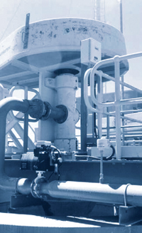
| Figure 1—Typical froth flotation cell process flow with flow meter. |
Froth flotation cells separate minerals from ground-ore slurries based on the difference in the hydrophobicity of the minerals and the ore waste tailings. The process separates the lighter minerals from the heavier waste tailings. Pulverized ore particles are fed downward via a pipe into a large tank where they are mixed vigorously with water, a reagent that promotes attachment of valuable minerals to air bubbles and compressed air.
The result is a slurry mix of mineral-laden bubbles that travels upward to a collection zone where the valuable minerals are gathered and sent on for further processing (Figure 1).
Froth flotation cells rely on precision froth handling for increased recoveries in roughing, scavenging and cleaning applications. Accurate and repeatable mass air flow measurements are vital for the efficient operation of large flotation tank cells and reduced reagent costs.
THE PROBLEMS
The customer performed a careful process review of its flotation cell performance and determined that the compressed air flow meters were not delivering accurate and repeatable readings. The inaccurate readings meant that sometimes not enough compressed air was being piped into the frother unit.
The existing flow meters were volumetric and not mass flow measurement meters. As the pressure and temperature of the compressed air changed, the volumetric flow meters could not adjust for the change in mass air flow. There also was not enough pipe straight run to create a repeatable flow profile, which again affected accuracy and consistency of measurement.
 |
| Figure 2—Froth flotation cell installation. |
Measuring mass air flow (rather than volumetric flow) is critical to the efficiency and stability of the frothing process due to the large variations in ambient air temperature that occur in comparison with the smaller changes in slurry temperature. The measured air flow is closely related to the air or bubble volume within the flotation tank. Therefore, measuring mass air flow rather than volumetric air flow increases the frothing process performance efficiency.
Flotation cells are “aerated” with compressors or blowers and often with very little pipe straight run, which can affect the accuracy and consistency of flow meter readings. Larger processing plants also utilize modern process control systems (DCS, PLC) to optimize their operations, and the flow meters must be able to communicate with them.
In this case, the flotation cells utilized 3-, 4- and 6-in. compressed air lines (Figure 2). The customer’s process review had revealed that the amount of unobstructed pipe straight run was insufficient and affected the accuracy of the flow meters.
The flotation cells required an air flow rate that varied from 35 to 1,050 SCFM depending on the location and production volume, and at pressures from 4 to 7 psig [0.3 bar(g) to 0.5 bar(g)]. Typical process temperatures were 32°F to 140°F (0 to 60°C).
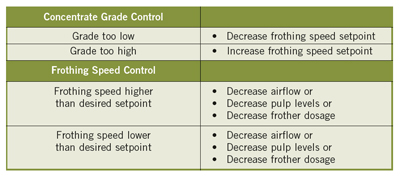
Flotation cells require precise control of compressed air because the frothing process efficiency is based on the speed of the froth as it moves from the surface of the slurry to the recovery area. The speed of the froth is controlled by the air bubbles induced into the flotation cell, tank level and reagent dosages.
Flotation cell technology is based on the operational principle that the frothing speed setpoint controls the concentrate grade. An example is shown in the chart to the right.
The accurate and repeatable measurement of the compressed air delivered to the flotation cell improves ore yields, reduces reagent cost, and provides a significant plant energy cost savings from reduced operation of the air compressors and blowers. The more efficient the frothing process, the less often the compressor runs, which reduces process energy costs. The amount of reagent consumed is also affected by the efficiency of the frothing process, which is another process cost savings related to the accuracy of the compressed air mass flow measurement. The repeatable control of the mass air flow therefore increases the frothing process efficiency.
 THE SOLUTION
The mineral producer contacted the process applications team at Fluid Components International (FCI) for advice about its compressed air measurement accuracy problem. The FCI team recommended its thermal dispersion ST100 Air/Gas Flow Meter (mass flow measurement) combined with a Vortab Insertion Panel (VIP) Flow Conditioner to eliminate the problems with the insufficient pipe straight run.
The meter’s mass flow sensor, with its temperature-compensated design, eliminated the accuracy problem. Its adjustable 1- to 6-in. insertion length was compatible with all the pipe sizes in use and its Profibus PA digital bus communications were compatible with the plant DCS system.
The installation of the flow conditioner at three pipe diameters upstream of the meter locations on the frother unit solved the lack of pipe straight run availability. Conditioning the flow resulted in a highly repeatable flow profile across the entire required flow measurement range, which helped solve the accuracy and repeatability issues.
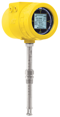 |
| Figure 3—ST100 flow meter |
The recommended mass flow meter (Figure 3) is a next-generation advanced design, offering feature-rich and function-rich electronics. This highly adaptable meter allows users to select a meter for today’s measurement requirements, but have the flexibility to change in the future as process requirements or equipment changes.
The customer selected the new mass flow meter in part because of its Profibus PA digital communication capabilities. It also supports 4-20 mA analog, frequency/pulse, or other digital bus communications such as HART, Foundation Fieldbus H1 or Modbus. If a plant’s needs change over time, the meter adapts as necessary with a plug-in card replacement that can be changed out in the field by a plant technician.
The mass flow meter’s unique graphical, multivariable, backlit LCD display/readout allows plant technicians to view process information locally as necessary at the point of installation. It provides a continuous display of all process measurements and alarm status, and the ability to interrogate for service diagnostics.
This user-friendly mass flow meter stores up to five unique calibration groups to accommodate broad flow ranges, differing mixtures of the same gas and multiple gases, and obtains up to 1,000:1 turndown. Also standard is an onboard data logger with an easily accessible, removable 2-GB micro-SD memory card capable of storing data for up to 90 days.
The mass flow meter chosen for the plant can be calibrated to measure compressed air or virtually any process gas, including wet gas, mixed gases and dirty gases. The basic insertion style air/gas meter features a thermal flow sensing element that measures flow from 0.25 to 1,000 SFPS (0.07 NMPS to 305 NMPS) with an accuracy of ±0.75% of reading, ±0.5% of full scale.
For safety, the mass flow meter is agency approved for hazardous environments, including the entire instrument, the transmitter and the rugged, NEMA 4X/IP67 rated enclosure. Instrument approvals in addition to SIL-1 include ATEX, IECEx, FM and FMc for product reliability.
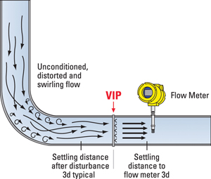 |
| Figure 4—Vortab VIP panel. |
To support the plant’s frother cell facility layout, the insertion panel type flow conditioner (Figure 4) was installed upstream from the mass flow meters. The flow conditioner provides a low pressure-loss solution to flow profile irregularities produced by elbows, valves, blowers, compressors, and other disruptions that commonly occur in pipe and duct runs.
The flow conditioner’s design combines proven swirl removal technology with a unique mixing process to achieve the most thorough and efficient flow conditioning available. Tabs are located strategically within the conditioner that promote rapid mixing, creating a uniform flow profile for proper measurement by the meter.
THE OUTCOME
Lower compressor run-time energy expense, along with less reagent use, combined to achieve more than 7% total cost reduction, which paid for the new flow instrumentation in only one month. The installation of the rugged mass flow meter and flow conditioner solved the frother unit’s measurement accuracy and repeatability problems and increased the unit’s output efficiency.
The single-tap insertion style thermal mass flow meter and the insertion panel flow conditioner were compatible with the concentrator’s existing piping for easy installation. The flow meter’s Profibus PA digital communications smoothly integrated directly into the existing DCS system with reduced wiring and commissioning cost.
The thermal dispersion flow meter’s direct mass flow measurement and real-time temperature compensation ensured accurate measurement. There also was no need to install additional temperature or pressure sensors, which are required by some flow meter technologies. With the thermal mass flow meter’s “no moving parts” construction, there is nothing to break, clog or foul, and there is virtually no maintenance with excellent reliability, which is well suited for the harsh environment in mineral processing operations.
Steve Craig is a senior member of the technical staff at Fluid Components International.