


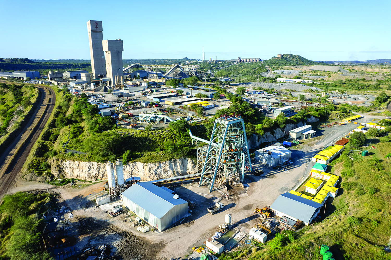
The PMC Lift 2 expansion project is expected to extend the life of mine to at least 2038. (Photo: Murray & Roberts Cementation)
Five hoist-and-shaft solution and service suppliers tell how they innovated to achieve critical goals and needed results
By Jesse Morton, Technical Writer
At a key meeting early in a project to sink a shaft in poor ground conditions, project and mine leadership agreed to sacrifice speed for safety. It was a critical decision. The move would come at a cost. Extra steps were taken. A non-traditional process was applied. Deadlines were pushed out. And ultimately, the project tallied an almost sterling safety record doing what historically was highly dangerous work.
The supplier achieved its goal by focusing on priorities, and by breaking from protocol when protocol clashed with those priorities. It is a recipe for success found in recent news stories by at least four other suppliers in the space.
When a hoist refurbishment project caved to inertia, strict project management discipline and the willingness to take some steps out of order brought it back on track. When a steel-lined shaft prohibited welding mast connections, alternative elevator infrastructure solutions had to be devised. When traditional wood guides for personnel cages hoisted by drum hoists simply can’t meet the standards of the new era in safety, steel guides and a new safety brake would be invented. As batch-haulage costs spike as mines move deeper underground, a continuous hydraulic ore-hoisting system is preparing to enter the market.
In each case, the challenge presented was complicated by entrenched traditions and expectations. In each, it was answered by thinking outside of the box. In each, the win was tremendous.
Safety Taken to a New Level
Murray & Roberts Cementation said the Palabora Copper Mine (PMC) ventilation shaft, now within 250 m of reaching its target depth of 1,200 m, shows how innovative methods and processes can solve key challenges and, importantly, ensure safety.
“For Murray & Roberts Cementation, the lessons learned on this project has shown the industry that we can provide a viable alternative method of shaft sinking that takes safety to a new level,” said Fred Durand, senior project manager.
Early in the project, PMC prioritized safety. “By taking the PMC way, we accepted that the pace of sinking would have to be compromised,” said Sechaba Letaba, package manager, PMC. “This has proved to be a positive approach, as we have a fatality-free safety record on the project,” he said. “This is in stark contrast to the history of shaft sinking, which would often claim lives and injuries.”
Murray & Roberts Cementation adapted its Canadian shaft sinking method to the PMC way shortly after it was awarded the contract in 2019 to sink a new ventilation shaft to service the Lift 2 block cave. The Lift 2 expansion, a twin decline system to access ore below the Lift 1 block cave, launched in 2008 and is expected to extend the mine’s life to 2038.
Feasibility studies for the 8.5-m-dia. ventilation shaft “indicated that a blind sink was the optimal method, despite its higher cost and longer timeframe,” said Jas Malherbe, project manager, Murray & Roberts Cementation. “Ground conditions were among the reasons why raiseboring was not an option, as the side walls needed immediate support to prevent scaling.”
Two twin-boom Komatsu electro-hydraulic jumbo drill rigs do the drilling. “These are slung down the shaft from surface and nested in the four-deck stage for drilling the shaft bottom, a procedure which is repeated for each 48-hour blast-to-blast cycle,” he said. “Waste rock is lashed using a Komatsu excavator with a 0.36-m3 bucket, which is lowered from surface through the stage to shaft bottom. An 10-mt kibble transports the waste rock to surface.”
The main challenges faced were defined by the ground conditions, “but the extent of the difficulties exceeded expectations,” he said.
Murray & Roberts Cementation responded “by taking the shaft lining right down to the blasted face,” Durand said. “Traditionally, the shaft would be lined to within 12 m to 18 m of the shaft bottom, with the sidewalls being temporarily supported with split sets and mesh,” he said. “The poor ground conditions prevailing where the vent shaft is being sunk led to high levels of scaling that made this practice unviable.”
The shaft was lined with permanent support after every 3 m of advance and within 48 hours. “We use a specialized concrete mix for rapid setting and early strength that hardens to 3 MPa within 4 hours,” Malherbe said. The concrete is in place for at least 8 hours before blasting.
“This solution requires that the blast is conducted while the shutters are still in place, so the shutters were strengthened and a toe added that would better handle the blast,” he said. “The exposed concrete above the shutter is able to withstand the blast, as it has already cured for 48 hours.”
The lined sidewall reduces the risk for personnel doing the drilling and installation of temporary support. The cycle is choreographed so the shaft bottom is lashed, cleared and drilled while the concrete sets.
“Lashing a shaft with an excavator is not a new idea, but it is usually a back-up method to the cactus grab,” Letaba said. “We decided that the excavator would be the primary lashing method, to further enhance safety on site.”
The headgear was automated. The winding engine driver uses a camera for visibility when hooking the kibble for tipping.
“We also opted to use electric actuators in this project, rather than the traditional pneumatic and hydraulic cylinders on equipment such as the bank doors, swing chutes and tipping chutes,” he said. “This has allowed us to mitigate the risks such as hearing loss from the noise of certain actuators, and contamination from oil leaks.”
Rope twisting sometimes affected the orientation of the stage. “Other unexpected challenges in the project related to keeping the winder rope performance within the stringent safety standards we observe, and the replacement of a winder drive to ensure optimal performance,” Malherbe said.
Suboptimal fragmentation was common. “This is a factor that is managed within the project, being satisfied that our focus on safety is well balanced against the pace of production,” Durand said. “On the mining side, we were able to make certain adjustments with regard to blast patterns and the types of explosives that we use.”
The inevitable large rocks were broken using a hydraulic breaker coupled to the excavator. “As a team, we decided that the rock breaker was the right solution for the issue of oversized rocks, and it was accepted that this would have an impact on the cycle times,” Malherbe said.
It slowed progress, but “it is still the safer option,” Letaba said. Another safer option is eliminating concurrent work. “For instance, no one is allowed in the shaft bottom while people are lining the shaft from the stage.”
The project showed that it is effective to review key performance indicators from prior projects when innovating and problem solving, Durand said. “It may not be possible to work differently while still trying to meet the same KPIs,” he said. “A good example is the use of an excavator for lashing, which is safer but takes longer, even without the occurrence of large rocks.”
It also showed the importance of close coordination with the customer. “Unexpected challenges tend to have an impact on scheduling, so the strong relationship of trust with our customer, PMC, was vital to solving any issues as they arose,” Malherbe said. “Our approach has always been to work closely with customers on solutions, and to ensure they are regularly updated on progress.”
Ultimately, the shaft will prove to be a “success story that reflects well on the strong collaboration between PMC and Murray & Roberts Cementation, as we both stood strongly by our safety commitments to find a way through the challenges,” Letaba said.
The partnership delivered the results desired by both parties, “with PMC’s vision aligning closely with ours and driving the project’s direction very constructively,” Durand said.
PMC, located near the town of Phalaborwa in South Africa’s Limpopo province, began production in 1956. It produces 50,000 mt of copper ore per year.
Project Management Discipline Scores Win
Alpine Consulting and Mining Engineering PLC said the successful completion of a hoist refurbishment and installation project at a hard rock metal mine in northern Idaho is a “tremendous win” for both the miner and the company.
“We ended up coming in right on the baseline schedule that was developed back in the first part of February, almost to the day,” said company owner and principal engineer Bracken Spencer, project manager on the installation.
“Pre-commissioning and commissioning went off as best as could be expected, minus a couple little hiccups and run-ins,” he said. “For the most part, we got everything done. The system is now functioning. Shaft rehabilitation is underway.”
The successful completion of the project resulted from disciplined planning, coordination and communication and demonstrates the value of strict project management protocols. “Using a fairly collaborative effort by the engineers, leaning on the expertise of the various contractors, and through multiple coordinating meetings throughout the week, we truly experienced very minimal downtime in the schedules, and minimized risks from delays,” Spencer said. “And since we set a baseline schedule back in February, those target dates that were communicated on that original baseline schedule held true through even the final phase of commissioning.”
Alpine Consulting and Mining Engineering was contracted after the project had bogged down for what the miner had hoped was the last time. The project was big and complicated, and critical to a mine seeking to expand production and increase revenue.
The shaft dates back to the 1940s. “About five years ago it was taken out of service due to safety concerns of both the safety apparatus and structural concerns on the head frame and the sheave wheels,” Spencer said. “The mine began the process of procuring the refurbished hoist, working with W.G. Spencer Engineering,” he said. “The old hoist was completely removed and the hoist that is going in was a hoist from a different location.”
That unit, a 181-in.-dia. double-drum single-clutch hoist, would first be rebuilt. It uses two 500-hp-DC motors, allowing a speed of 1,000 ft/min. to a depth of 6,000 ft. Initially it will be used for men, materials, equipment, bolts, drills, and regular consumables.
“All components were returned to their original specifications along with specific upgrades that were determined by the engineering group,” he said. “And then were delivered to site, and the interior of the hoist house was excavated and all new flat work was put in, and then the hoisting unit was set in place.” The hoist house was rebuilt, and a digital communications solution for the system installed.
The solution could support automation, “more process integration, remote access for data acquisition, and would help the miner design mine plans around the capacity of the shaft,” Spencer said. “Actually understanding what the hoist itself is producing, the uptime and availability, is going to help support planning and accounting.”
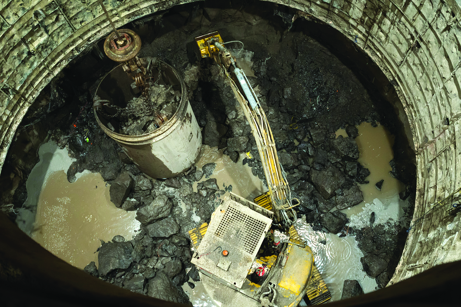
Above, an excavator busy lashing at the shaft bottom with shaft lining being carried out on the face. (Photo: Murray & Roberts Cementation)
Historically, any data related to the old hoist system was generated and stored manually. The new system would log and organize data from multiple points within the system, and then generate historical information when requested. “The data can, with an emphasis on can, be used for both predictive and future prescriptive maintenance,” he said. “That will require the use of either CMMS software systems or other machine learning systems to analyze and evaluate the data generated.”
The project progressed but not without setbacks that threatened the goals of the miner. By January, the shaft had been without a functional hoist for a half-decade. For the last couple of those years, Alpine Consulting and Mining Engineering had been doing engineering and other work related to other projects at the mine.
The opportunity was floated for a third-party company to evaluate and drive the project across the finish line. “They reached out directly to me,” Spencer said. “And understanding the importance of this to their operations, I jumped in the truck literally the next day and drove out there, had a 4-hour sit-down and talk-through on what I could offer and what my vision for this would look like,” he said. “And then drove back that night and was notified the next day.”
The consultant was tapped for project management of construction and commissioning. Stakeholders included in-house management and project management, construction and installation contractors, and an outside engineering firm “to design and oversee the specifics of the integration of the refurbished hoist,” Spencer said.
“I was brought in for this project in January to make sure it was going to be wrapped up on a newly defined schedule and budget,” he said. At that point the final deadlines were loose and the budget was vague. “It was very much ‘we are just going to get things done when we get it done,’” he said.
“That was one of the first things I did when I was on the project was to define what the outstanding work was and the path to complete everything,” Spencer said. “And then understanding what the expenditure rate had been, and based on the work yet to be done, build an estimate for completion that is with the appropriate applied contingency that we will be coming in right on track.”
The challenges presented stemmed from the sheer size of the hoist, the need to minimize downtime, and the peculiarities of the stakeholders. “One of the difficulties is dealing with vendors and contractors from all over the continent, different time zones, different countries, and trying to coordinate materials to be here when needed, and personnel to be here from all over the country, or all over the continent, for their various parts and pieces, particularly on the commissioning front,” he said. “And managing that so that we are minimizing downtime without having undue standby time.”
One solution was the application of strict project management discipline. “We clearly defined and communicated what the business need of the project was on the front end and kept sight of that throughout,” he said. “We painted that bigger picture so that everything that is being done and being worked towards that end has a purpose to it, has a real cost and a real value.”
A defined cost, which could serve as a penalty, was assigned to any potential delay. “That provides, dare I say, leverage, to say this is why we need to have this done at this time and in this manner,” Spencer said. It also meant that the need for innovation was shared by the group and not pigeonholed.
Unforeseen challenges related to supply chain issues. For example, “we had a manufacturing delay in one of the components for the hoisting system,” he said. The delay could span as much as three weeks.
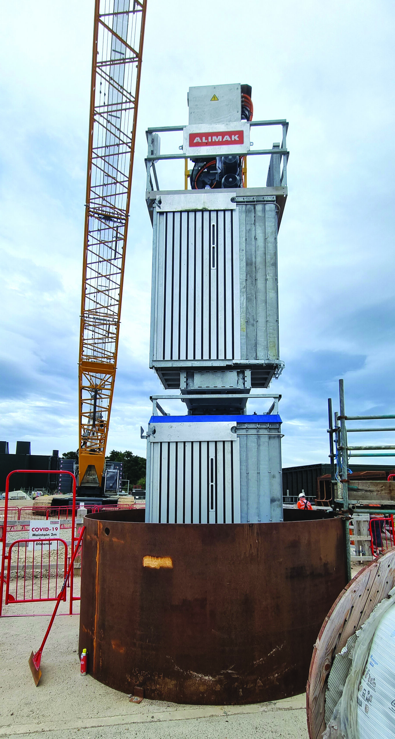
At the Woodsmith mine, each Alimak elevator measured 1.56 m wide by 1.04 m long by 2.17 m high. Above, the elevator is installed into the shaft (Photo: Alimak)
The solution was to do some work out of sequence. Knowing it would cause future rework, and while awaiting the parts, “we decoupled the hoist drum from the motors, after they had already been aligned and coupled, to allow for testing of the motors and the initial tuning of the drive that will control the motors,” he said. “By doing a little bit of rework to bring ahead certain portions of commissioning, we were able to come back around and maintain our schedule.”
The successful completion of the project showed the importance of using project management. “Sometimes that can be done in-house. Sometimes that has to be farmed out to an outside firm,” Spencer said. “Getting an outside perspective can be a great strength and asset for people to see things or for someone to get a perspective that they need because they have been so ingrained in their operation for so long.”
The success also is the result of differentiating roles. “A mine has to know when a project needs both a project manager and a project engineer,” he said. “In the mining world we like to try and do everything. Sometimes there is a time when you can’t do everything,” he said. “For this one I wore the project manager hat and I did a lot of work mentoring the individual who was the project engineer and actually to that end that made it a very good opportunity.”
The project served as a staple for Alpine Consulting and Mining Engineering for H1 2023. “It has not only furthered the relationship between this client and myself but also provided a strong foothold in the Silver Valley for work that I’m doing up there,” he said. “This has been just as important a project for me as it has been for mine.”
Customized Solution Solves Challenges
Alimak Group reported the 900-kg-capacity double-decker Alimak SE 900 FC elevator car at Woodsmith potash mine in North Yorkshire, United Kingdom, is performing as designed and garnering positive feedback from the miner.
The unit offers “smooth and reliable vertical access 24/7,” said James Humphrey, industrial division manager and project manager on the design and delivery.
The elevator car was designed to move 18 people 370 m in a steel-lined shaft of an “incredibly limited” size, Alimak said. “Alimak’s design engineers developed a custom double-decker rack-and-pinion elevator, comprised of two elevator cars, interconnected one above the other,” the company reported. “Each elevator measured 1.56 m wide by 1.04 m long by 2.17 m high, with each car able to hold a maximum of nine passengers.”
The steel lining of the shaft prevented welding mast connections. “Due to hot works within a small space creating a ‘confined space,’ the risks and program implications of welding meant a lower-risk solution needed to be found,” Humphrey said.
The challenge was without precedent for Alimak. “Alimak worked with Hilti to develop a new solution, which involved the use of friction-welded studs, which were fired into the elevator shaft using a spring-loaded gun,” Alimak said.
Stud design was based on preexisting Hilti solutions, Humphrey said. “Hilti had the fastening solutions for secondary fixing of ducting, conduit and cable tray brackets to primary steel, so this was investigated by the design team,” he said. “The fixing solution was four M8 X-BTs within each wall bracket, in S355 steel, with recommended loads of 4.6 kN in tension or 5.3 kN in shear.”
Using the spring-loaded gun “reduced the risks of fumes produced by the traditional explosive cartridge type,” Humphrey said.
Metrics on the elevator car can be tracked by the mining maintenance teams by using My Alimak, a custom web-based portal developed by Alimak Group. “Using the My Alimak portal, Strabag AG can view operational data and statistics relating to their elevators, which allows them to manage their assets more efficiently.”
Data on the car is communicated by the WIFI system for the shaft, Humphrey said. “A WIFI router connected to the main lift controller supports the shaft-integral WIFI network in combination with Mobile GSM Networks to transfer real-time data on operational status and diagnostics.”
At WoodSmith, mined material from the 1,600-m level is hauled to the 370-m level and loaded onto a conveyor that goes 37 km to the handling facility.
Innovative Design Aces Testing
FLSmidth introduced the Cage Guardian Safety Brake for steel guides, the skip Crank Type Dump Mechanism, and a new onboard Conveyance Battery Charging System. “These three solutions improve operational safety and sustainability within the mine shaft,” said Matt Goddard, head of mine shaft systems. “Innovation with a focus on lowering operating costs while reducing the environmental impact further supports our industry through objectives set out in FLSmidth’s MissionZero Program.”
The Cage Guardian Safety Brake has been successfully developed, tested, and proven to meet regulations. “The Cage Guardian uses traditional spring-actuated mechanical activation to effectively clamp onto the guide while an independent braking system mounted to the cage dissipates the kinetic energy to stop and hold the cage,” said Henry Laarakker, product manager, mine shaft systems.
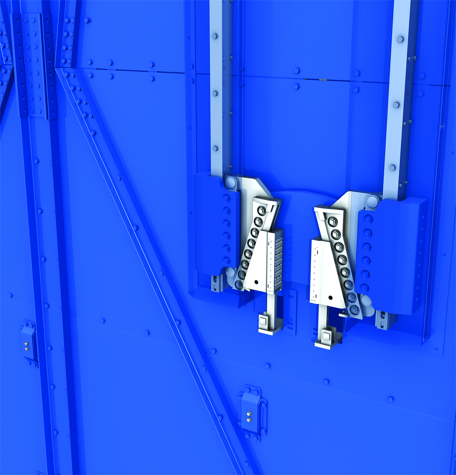
For use on steel guides, the Cage Guardian Safety Brake was designed and tested to meet some of the most stringent regulations. (Photo: FLSmidth)
The design represents an evolutionary step beyond the traditional, conventional safety catches.
“For decades, many North American mine shafts have operated using wood guides for cages transporting personnel when hoisted via a drum hoist with a single head rope attached to the conveyance,” Laarakker said. “Safety in transporting personnel in a vertical mine shaft is imperative, and redundancies are set in place to ensure safety requirements are met,” he said. “North American regulations require such a cage to have a safety device, which conventionally has been a dogging-type mechanism relying on the resistance obtained from individual teeth carving out the wood from the guides, providing the deceleration forces necessary to arrest and stop the cage anywhere in the shaft.”
Wood guides are less than ideal for the application and compete poorly against engineered steel guides, he said.
Those defects and distortions can grow over time and impact performance. “Any event in which a dogging-type safety mechanism becomes activated requires the complete replacement of the damaged wood guides,” Laarakker said.
Engineered steel guides can last longer, and testing for the Cage Guardian Safety Brake showed that they perform to specifications. “The Cage Guardian was designed to meet some of the most stringent regulations, primarily Ontario Mining Regulation 854,” Laarakker said. “This means that it is subjected to free-fall testing.”
Cage free-fall tests simulated the hoist reaching operating speed “under full equivalent personnel load,” the safety catch deploying, and the skip slowing “to a stop at an average rate of not less than 9 and not more than 20 m per second (m/s), or 0.9 to 2 gravities,” Laarakker said. “A large percentage of the development tests were performed in a multi-story test tower using full-scale prototype test rigs, in addition to a scaled-down brake stand for more detailed examination of braking characteristics.”

The new Crank Type Dump Mechanism is a skip-discharging mechanism that can increase hoisting capacity through reduced cycle times. It can help increase production rates by as much as 10% or more. (Image: FLSmidth)
Testing ranged from a two-guide empty-cage scenario in a drop test, or a quick-release test, to a fully loaded four-guide test rig at free-fall simulating a hoist speed of 7 m/s. “The various components were subjected to rigorous tests and detailed improvements to ensure performance levels and reliability,” Laarakker said.
“The tests included investigation on hollow structural steel guides contaminated with water and grease as well as hot dip galvanized coatings,” he said. So far, roughly 300 tests have proven the system meets requirements. “The latest tests verify performance for the Cage Guardian for large four-guide cages with synchronized actuation, a cage load of up to 28,500 kg, and a hoist speed of 7 m/s, effectively capturing the largest range of cage size normal for single-rope conveyances.”
Separately, the new Crank Type Dump Mechanism (CTDM) is a skip discharging mechanism that can increase hoisting capacity through reduced cycle times verses conventional scroll-type discharge.
Historically, discharge scrolls, mounted to the headframe, are widely used. They are reputed to “offer the lowest initial installed capital cost, but only if consideration isn’t given to the additional headframe height requirements,” Laarakker said. The skip must rise significantly above the dump lip, thus increasing the headframe height requirements.
“Additionally, static scrolls do not use any operating energy to discharge the skips but will require some additional hoisting effort with every dump,” he said. “Besides added headframe elevation, the total hoist cycle time increases due to creep speed of the skips passing through to the point of reaching maximum opening.”
At less than 0.6 m/s, creep speed is not a misnomer. “This prolonged cycle time compromises the achievable overall daily production tonnage,” Laarakker said.
Thus, the CTDM reduces cycle time. It eliminates “this extra travel distance and time at creep speed, improving skip efficiency by allowing shorter skip dumping and filling times,” he said. The reduced cycle time leads to “increased production rates of as much as 8% to 10% or more.”
Simple in design, the CTDM also lowers energy consumption over hydraulically operated dumping mechanisms. It “dynamically opens and closes the skip in a short burst of energy, realizing only a single open-and-close cycle through each complete skip cycle,” Laarakker said. “Hydraulically controlled systems are continuously energized and operate on standby for most of the time while actually providing any useful output less than 10% of the time.”
With an electro-mechanical drive, the design reduces system complexity, which offers multiple benefits, Laarakker said. “Of special value is that the need to control acceleration and deceleration of hydraulic cylinders as they are retracted and extended in short bursts is replaced by the natural sinusoidal curve representing the dynamic motion of the crank,” he said. “High-pressure lines, risk of fire from hydraulic fluid, and maintenance intensity and complexity are all other factors that favor a simpler electromechanical solution such as the CTDM.”
Also offering efficiencies that can ultimately translate into cost savings, the new onboard Conveyance Battery Charging System uses the kinetic energy of the skip to continuously charge batteries for the onboard communication system. “This not only simplifies maintenance requirements but uses inherent energy through hoisting instead of relying on external energy sources to recharge batteries,” Laarakker said. “The new system is compact and easy to mount using FLSmidth’s own heavy-duty guide rollers and is an efficient and effective way to replenish battery charge.”
Revolutionary System Preps for Scale-up
Weir Minerals completed testing of an industrial-scale prototype of its GEHO Hydraulic Ore Hoisting (HOH) pump system and is preparing the next step of scale-up and field qualification.
In tests at its Venlo Technology Hub in the Netherlands, the prototype “operated well within the comfort zones,” raising the solution’s readiness level, said Venlo Technology Group’s chief engineer, Ralph van Rijswick.
“The GEHO HOH pump system presents new possibilities in various applications,” he said. “For underground mining, it provides an alternative to skip hoisting.” For example, at some greenfield operations, “the CAPEX related to sinking a new, large-dia. shaft with the required hoisting infrastructure would be significantly higher than the HOH system.” More importantly, because the GEHO HOH pump system operates continuously, it can offer production rates superior to those offered by batch haulage systems.
Weir Minerals launched the development of the system in 2018 to address the shortcomings of existing pump technologies. The resulting GEHO HOH pump system is based on pressure exchange technology.
In the flowsheet, HOH is between ROM blasting and the first ore processing stage. It can handle the entire pebble size range or can be scaled up to cover the cobble range. “In all likelihood underground primary and secondary crushing will be required before the ore slurry can be fed into the HOH system,” van Rijswick said. It could also require the “separate hoisting of coarse and fine fractions when using, for example, an existing capacity-limited skip hoisting system in parallel.”
After crushing comes slurry preparation, where the solids are mixed with the carrier fluid. “The slurry preparation stage can be a sump or hopper into which dry solids can be fed by a conveyer belt,” he said. “A centrifugal slurry pump then draws the mixture from the hopper and feeds it into the system at relatively low pressure.” Separately, a GEHO PD slurry pump feeds fluid into the high-pressure inlet.
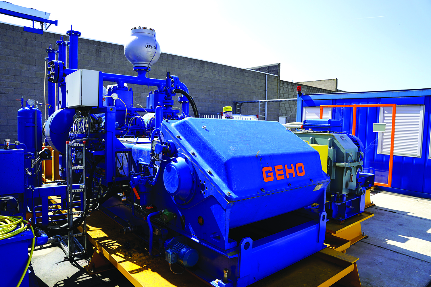
Weir Minerals GEHO hydraulic ore hoisting pump, with design improvements over predecessor pumps, completed testing; and the system is ready for scale-up. (Photo: Weir Minerals)
The GEHO PD pump provides a constant high-pressure flowrate regardless of the pressure acting on the pump, “which is essential to prevent solids sedimentation and riser blockage,” van Rijswick said. “PD pumps can handle slurry with small particles, which means the driving fluid doesn’t have to be clean and free from solid particles,” he said. “They also have high pressure capabilities and are energy efficient.”
In the system, “the pressure from a high-pressure driving fluid flow is transferred to a low-pressure pumped fluid flow,” van Rijswick said. “The design uses a horizontally oriented open pressure exchange system with actuated pumped fluid valves.”
A valve is on each end of the pressure exchange chambers (PEC). “A single PEC is basically a pipe with actuated valves on both ends,” he said. “Mixture inlet and mixture outlet valves are located on the right-hand side of the chamber, while driving fluid inlet and driving fluid outlet valves are located on the left side. A compression and decompression valve is located in parallel to the driving fluid inlet and outlet valves.”
The PECs are arranged in a series, and fill and empty consecutively. Within each, the slurry mixture pushes the driving fluid flow out. “The driving fluid displaced from the PEC is then re-used as carrier fluid in the mixture preparation stage,” van Rijswick said. Next, “A high-pressure driving fluid drives the mixture out at high pressure into the discharge connection of the system.”
The action provides a continuous flow to the outlets. A low-pressure driving fluid outlet feeds a carrier fluid supply tank. A high-pressure mixture outlet feeds the mixture riser to the surface.
On the surface, “the carrier fluid is separated from the hoisted ore in a dewatering stage,” he said. “The carrier fluid is then re-used as driving fluid.”
The ore can then be transported via conveyor belts, trucks or rail, or can be fed directly into the comminution circuit.
The system offers a continuous movement of ore to the plant, which can be preferable to trucking and skip-hoisting material in batches. “Most traditional vertical transportation methods operate in batch mode and have limitations in capacity, especially when operating at greater depths and high throughputs,” van Rijswick said. “For instance, as an operation goes deeper underground, the distance the material needs to be transported increases and, as a result, capacity is reduced.”
Truck haulage, while a relatively low-CAPEX solution, incurs fuel and labor costs, meaning higher OPEX. “Moreover, in a 24/7 production environment, and because of limitations related to the size of the shaft, skip, cable, and winding motors, trucking and hoisting systems can’t be easily scaled up,” he said. “And, in terms of sustainability, it’s an extremely carbon-intensive solution.”
In contrast, HOH systems are “scalable to any required capacity,” van Rijswick said. “This is achieved by increasing the size of PECs for the required flow rate and more multiple PD pumps.”
Future feasibility testing of the system “will be site and operation specific and include examinations of downstream processing and logistics requirements,” he said. “The accessibility of the ore body is another important factor to consider: Can a raise bored shaft be used or does a new shaft need to be sunk? How close can the shaft be located to the ore body?”
“HOH could provide easier access to the ore body,” he said, “with potentially huge savings in underground development work.”


