


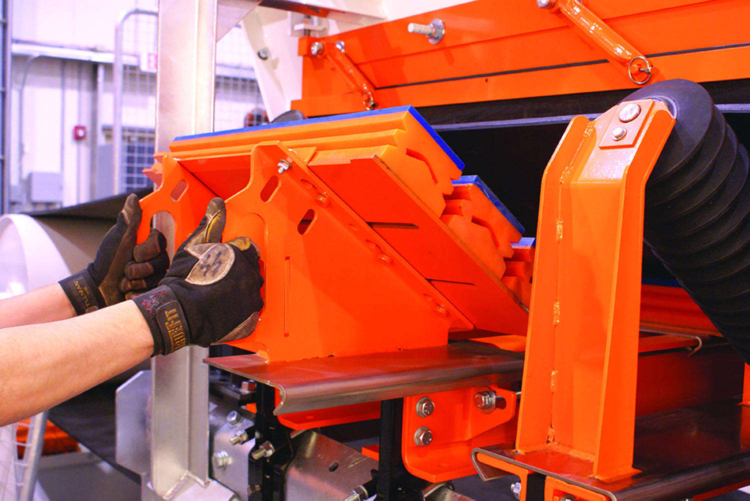
In addition to adverse impacts on output, plant items that require constant maintenance raise the probability of worker injuries, particularly when dealing with clogged chutes or accessing hard-to-reach transfer point components. Slide-in/slide-out belt cradles such as this model from Martin Engineering can help solve both safety and maintenance-resource issues. (Photo: Martin Engineering)
Attention to the design and maintenance of feeders, chutes and transfer points often can eliminate or reduce material flow problems that degrade plant output
By Russell A. Carter, Contributing Editor
Mineral process-plant design is focused on devising the most efficient method for turning highly variable, marginally valuable raw material into a consistent, high-value product. How valuable that product actually is depends heavily on market trends, but how consistent it is – in terms of available quantities, stability of output and content – is strongly influenced by plant layout and operational routines. Anything that slows or disrupts the intended flow of material through a concentrator will most likely result in inconsistent production and a variety of problems.
Opportunities for flow disruption can occur anywhere in the plant where material in the product stream changes location, direction, angle or speed of transport. In other words, anywhere along the process stream that a feeder, chute, gate or conveyor transfer point is located.
In an industry that’s notorious for subjecting its equipment to incredibly tough usage, the feeders, chutes and transfer points used throughout its mills are at the extreme end of the rough-duty spectrum, probably only surpassed by crushers and breakers when it comes to the ability to function efficiently while withstanding the impact of thousands of tons per day of raw, often abrasive material falling from above – and throughput demands are constantly rising. The largest apron feeders from suppliers such as FLSmidth, McLanahan, MMD, Weir and others can handle volumes in the five-figure tons-per-hour range; in fact, one major Nordic supplier recently announced a contract calling for delivery of a 900-hp apron feeder – one of the largest it has ever built – to supply material downstream to one of its large primary gyratory crushers for a mine in the Americas. That company’s feeder line can offer up to 17,000 t/h capacity.
These mechanical devices are important simply because they control the rate of material transfer from one point to another. Due to physical constraints such as headroom or floor space limitations, engineering oversight or capital constraints that influence equipment selection, they don’t always get the attention they merit. And, as newer concentrators get larger and more complex with multiple parallel process lines, any flaw or failure trend in one feeder, chute or transfer point in one line can emerge in other lines as well.
Inconsistent material flow can cause excessive dust or spillage, loss of valuable content, reduced production capability and higher maintenance costs. Incorrectly designed conveyor transfer points may lead to poor conveyor belt tracking, belt wear along the skirt lines and rapid skirt liner wear, while improper chute layout can result in similar problems as well as reduced flow volume and velocity, ineffective surge handling and off-center belt loading. In the longer term, the design and capabilities of existing feeders and chutes may not be sufficient to accommodate future needs for higher throughput, or to handle a new type of ore that has different flow characteristics than the material they were originally installed to handle. And, plant items that require constant maintenance attention raise the probability of worker injuries, particularly when dealing with clogged chutes or accessing hard-to-reach transfer point components.
Overcoming this long list of worrisome ‘what ifs’ is a job best accomplished through collaboration of project owners and managers with engineering and equipment specialists. While mineral processing will always remain a somewhat inexact science due to the variability of raw input materials, new design tools and technologies can make it easier for everyone involved to identify feeder, chute and transfer point equipment that meets existing site requirements while minimizing the potential for plugging, excessive dust generation or particle attrition.
One of those tools is discrete element modelling, or DEM, a numerical technique used by an increasing number of process equipment suppliers since the 1990s to simulate particle flow dynamics when studying bulk materials behavior in a pre-defined three-dimensional defined geometry. As process equipment vendor FLSmidth, a long-time user of the technology, explains in its product literature, DEM software can produce animations that allow the user to visualize results that can be interpreted and used to develop and optimize new solutions or identify and eliminate existing problems. DEM can overcome the difficulties encountered when trying to evaluate certain material properties and volumes in the physical world, allowing users to run as many computerized what-if scenarios as necessary to evaluate changes in particle properties or find the best path for a retrofit project, for example.
Weba Chute Systems, a South Africa-based equipment supplier, uses DEM to predict:
• Bulk material flow patterns;
• Bulk material flow rates;
• Impact forces on particles and boundary surface;
• Wear patterns on boundary surface;
• Velocity profiles and dead zones;
• Particle distribution in segregation and blending.
Alwin Nienaber, technical director at Weba Chute Systems, explained in a recent blog post that technology and industry experience can be leveraged to obtain optimized solutions for chute design, either in an existing facility or a proposed project. 3D laser scanning of an existing layout will provide data that can be used to generate a precise 3D model, providing the basis on which necessary chutes and componentry can be designed and manufactured.
Keeping the goal of designing an optimal chute design in mind, he noted that while certain configuration changes could strain a client’s budget, a supplier’s depth of experience might prove useful in easing the cost impact. As a recent example, he pointed to a job for a South African iron ore producer in which Weba was asked to address the problem of an existing chute that needed attention every two days, severely hampering production.
“We designed and installed an optimal customized chute, but also recommended some related adjustments,” he explained. “The design was a split chute, and the plant needed to speed up its conveyor considerably, as well as raising the head pulley slightly, to achieve the necessary results.”
The changes recommended had financial implications, and the customer needed considerable certainty that the solution would be successful. To inspire confidence in its plan, Weba Chute Systems digitally modelled the proposed design and simulated its operation using software that visualized the optimal movement of material through the new chute.
He went on to note that ensuring the flow of sticky material at transfer points also can be a complex challenge. “This is where chute geometry plays a significant role, with experience informing the design of a chute to minimize impact forces and reduce material degradation. This can be achieved through the use of wear-resistant materials such as ceramic tiles or rubber linings, and further extend the service life of transfer points while reducing maintenance requirements.”
Viewing transfer points holistically should also include attention to other aspects in materials handling such as belt cleaning systems that can prevent carryback and also reduce material build-up at transfer points. Installing primary and secondary belt cleaners, along with belt tracking systems, can ensure that belts are free from sticky material carryback. This not only reduces the chances of blockages but also minimizes belt wear and extends belt life.
Experience Can Provide an Edge
Sometimes the material flowing through a chute can be both abrasive and sticky. As one recent example illustrates, working with a supplier that has prior experience with similar challenges can shorten the path to a solution. Chute Technology, an Australian company specializing in material transfer solutions, was asked by a copper/gold mining customer to fix a troublesome chute layout at the mine’s secondary crushing station. Material flow problems required the mine to keep workers constantly nearby to clear blockages, and component wear rates were excessive.
Due to the mine’s scheduled maintenance shutdown, work on improving chute performance had to be completed in eight weeks, instead of the six months it would normally take for this type of project. While design work could be done off-site with the latest flow enhancement and problem-solving technologies, the company explained, it was nevertheless a highly hands-on project that required Chute Technology to fit physical construction, installation, testing and commissioning around ongoing operations at a busy plant.
“One of the reasons we were able to deliver this project efficiently is that we already had the theory in place. Chute Technology had already developed the material flow optimization concepts for the coal industry, and the technical aspects were transferrable to this job,” said Chute Technology engineer Gian Naldi.
The project initially involved a chute for a double-deck vibrating screen with three outputs: fines, middlings and oversize. “The first chute we helped to optimize is under the vibrating screen and handles fines, which are highly abrasive and sticky. Working closely with the on-site staff who could exactly identify system requirements, we designed a chute that feeds the conveyor in the middle, with minimal impact compared to the old design, which had direct impact to skirts and belt. The optimized design loads between skirtboards, without contacting them. Skirtboards function only when there is a surge coming through,” said Naldi.
Work on the first phase of the project included:
• Flow modelling and surface design alternatives using DEM flow technologies to identify friction hot spots and hangup points, with production rate analysis for different throughput, including catering for fines and clay with high internal strength.
• Identification of existing bottlenecks and areas of construction where recurrent problems needed to be eliminated, including uneven loading of conveyors from discharge chutes with mistracking issues, particularly on the first chute, re-engineered.
• Selection of optimum wear materials, including 50-mm-thick replaceable ceramic tiles to minimize recurrent production interruptions for replacement of worn components. Previous liners of different and thinner material could wear out in less than three months.
The results, said Naldi, were favorable enough to prompt the mine to extend the engineering developed by Chute Technology in the initial phase to other areas throughout the entire plant.
Staying One Step Ahead
The mechanical concepts associated with feeders, conveyor belts and their ancillary equipment such as chutes, transfer and loading points originated more than 150 years ago, but suppliers continue to develop new designs aimed at solving persistent problems – many of which also date back at least 150 years while others have emerged due to the changing nature of the industry. Here are just a couple of examples:
Martin Engineering, a bulk material handling solutions provider, has “reimagined” the concept of a bulk handling transfer chute to reduce downtime for installation and offer more options for future modifications. The company said its new Transfer Point kit includes modular horizontal loading zone, settling zone, and stilling zone configurations, providing easier installation and a wider variety of chute options while facilitating future upgrades.
“This is a solution designed to fit most standard conveyors and belt widths, regardless of what material is being transferred,” said Dave Mueller, conveyor products manager at Martin Engineering.
The kit, as described by the company, is a heavy-duty horizontal enclosure that can serve as a loading zone, settling zone, and stilling zone. The width and length are determined by the receiving belt’s width and speed and the dust characteristics of the material being transferred. Dustier applications may require a longer settling zone.
The innovations built into the new kit, said the company, solve three common problems. The first is that transfer chutes are normally shipped in different packages that sometimes don’t arrive at the same time. Upon delivery, inventory is stored until scheduled downtime, increasing the chance of loss or misplacement. Another problem is, for most new transfer chutes on the market, some components can be prepared and assembled beforehand, but generally, new chutes need to be completely fabricated during downtime. The inability to build the structure before a shutdown increases the project budget and contributes to lost production time. The third problem is, after construction, horizontal transfer point chutes are commonly a single system that requires significant engineering and construction to be modified. Changes to existing transfer points can be challenging, but to accommodate new belt support equipment or adapt to increases in production, the chute is often raised or lengthened.
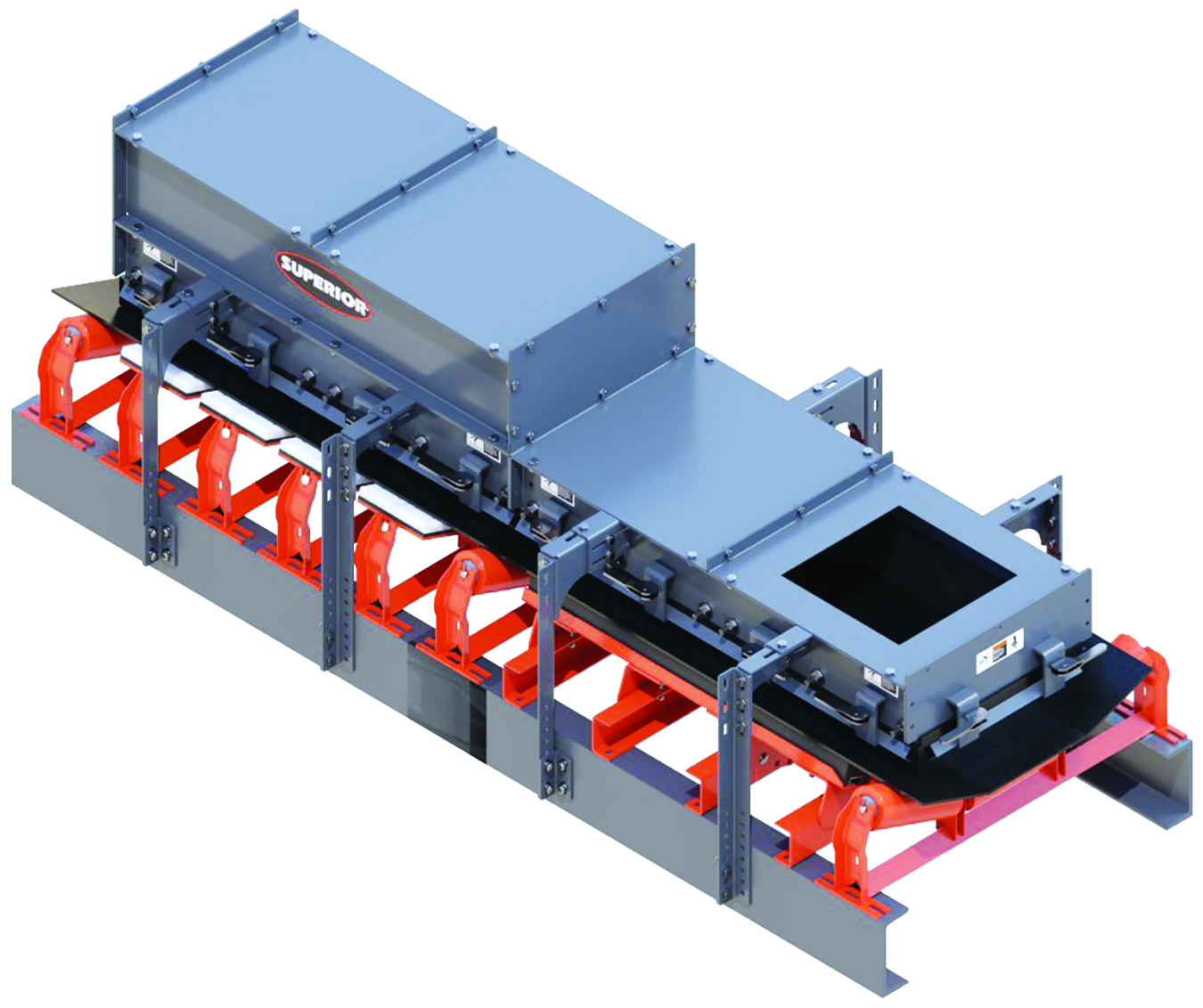
Superior Industries’ latest modular skirting system is designed for easy installation, according to the company, and controls both dust and spillage within conveyor loading and transfer zones.
To address these problems, the chute sections are delivered in a single crate with every component for assembly included. They can be assembled prior to the shutdown and installation, saving time and money, and are fully modular, making future changes easy without expensive construction projects.
The transfer point system accommodates belt widths of 18–72 in. (450–1800 mm) and an internal chute width of 9–59 in. (228–1498 mm). Each modular section is either 4 ft (1.21 m) or 6 ft (1.82 m) long and constructed of mild steel, 304 stainless steel or 316 stainless steel, with a thickness of 0.25 in. (6.35 mm), 0.5 in. (12.7 mm), or 0.75 (19.05 mm) to accommodate a wide variety of materials and conditions.
The taller loading zone controls air turbulence and connects to both the drop chute and settling zone. When cargo hits a belt with great velocity, fines and lumps splash up the sides of the belt. Without a properly sealed enclosure, the material will spill underneath the conveyor, creating a hazard, restricting access and fouling other components. The settling zone follows the loading zone and helps mitigate dust emissions. Dust is collected, mechanically filtered or settled back into the cargo stream prior to leaving the stilling zone and continuing as a conventional open air conveyor.
Superior Industries, another well-known US-based manufacturer and supplier of bulk material processing and handling systems, recently completed development of a new modular skirting system that the company said is easy to install and controls both dust and spillage within conveyor loading and transfer zones.
The new system can be retrofitted to any existing structure with little or no field fabrication, according to Superior. Two sets of adjustable legs aid in this universal installation. Additionally, easy to adjust clamping mechanisms are used in place of nuts and bolts to hold skirtboard rubber tight against the belt. An optional stilling zone is available to accelerate the settling of dust while material is moving inside the system.
Superior’s Modular Skirting System is sold in 5-ft (1.5-m) sections for conveyor belt widths up to 72-in. (1,728 mm).


