

An example of how a well-designed ground support system can withstand repetitive seismic events while allowing mining to proceed safely in troublesome areas
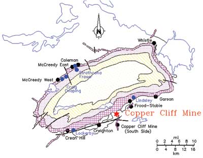
Figure 1—The Copper Cliff mine is located within the city limits of Greater Sudbury, Ontario, Canada, in a world-famous mining district.
The Copper Cliff underground nickel mine, owned and operated by Vale Canada Ltd., is located within the Copper Cliff Offset in the limits of the city of Greater Sudbury, Ontario, Canada, (Figure 1). The Copper Cliff Offset extends about 8 km south from the Sudbury Igneous Complex into the footwall rocks.
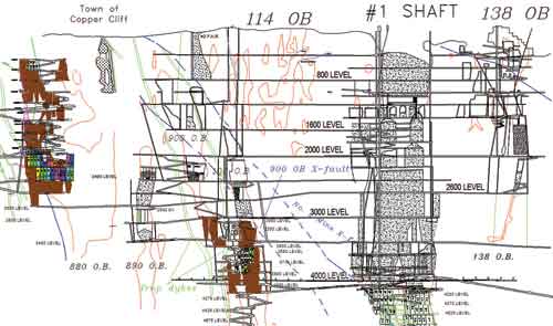
Figure 2—Location of two seismically active structures at the Copper Cliff mine: the 900 orebody cross fault and the quartz diabase trap dyke between the 100 and 900 orebodies.
Of all the major geological structures present at Copper Cliff mine, two structures are known to be seismically active: the 900 orebody cross fault, which strikes east-west and dips at about 55° north; and the Quartz Diabase Dyke (trap) located between the 100 and 900 orebodies striking east-west and dipping steeply north (Figure 2).
A review of the rockburst/seismic event history over the past 13 years at Copper Cliff revealed that approximately 40 rockbursts or other significant seismic events occurred in four different orebodies. Of these incidents, 35 (roughly 87%) took place within the 100/900 orebodies, and the remaining five incidents (almost 13%) took place in the 120 and 880 orebodies.
The 3.8-meganewton (MN) event that occurred on September 11, 2008, in the 100/900 orebodies following a crown blast was considered to be the most significant. Although the event occurred on 3050 level in the 100 orebody, damage extended across nearly a 300-m vertical block exending from 2700 to 3710 level. Approximately 3,000 tons of material were displaced at five locations on different levels. The damage was mostly associated with either the trap dykes and/or 900 cross fault. The support system at the damage locations consisted mainly of resin grouted rebars, mechanically anchored bolts in the back, and mechanically anchored bolts on the walls to 1.5 m above the floor installed through 6-gauge welded wire mesh. Shotcrete and cable bolts were used at some locations as a secondary support system. The installed ground support system was too stiff in nature and did not provide much yielding capability. Accordingly, the support system in place at the damaged locations was incapable of taking the impact of dynamic loading caused by the September 11 event.
A central blasting system was used and the Copper Cliff mine re-entry protocol after major seismic events was followed. No personnel injuries occurred due to these events.
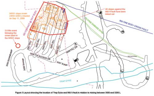
Figure 3—Location of trap dyke and 900 cross fault in relation to mining between 3050 and 3200 levels.
The September 11 rockburst was considered to be a result of mining the 94561 stope between 3050 and 3200 level. The location of the stope in relation to the major geological structures is depicted in Figure 3, which shows that there is a trap dyke between the 100 and 900 orebodies consisting of very strong material that is highly brittle in nature. As mining progressed in the 100 and 900 orebodies, it is very likely the trap dyke loaded up, resulting in significant seismic events/rockbursts.
Because all of the stopes along the 900 orebody cross fault were mined out between 3500 and 3050 level, the natural confinement that the orebody provided to the fault plane was removed. As a result, a major displacement might have occurred along the fault plane and caused the 3.8-MN event after the crown blast in the 94561 stope between 3050 and 3200 level on September 11. The crown blast could have triggered the slip and caused the event, which in turn triggered a series of rockbursts within the limits of the 100/900 orebodies and caused damage at multiple locations on different levels. Considerable time and resources were spent on rehabilitating all the damaged areas, and production was significantly impacted.
After this major event occurred, a rating system was developed to identify burst-prone areas at Copper Cliff and a revised ground support system was developed and installed in all of those areas, aimed at minimizing or eliminating damage to installed ground support or underground excavations in the event of future rockbursts.
Based on the guidelines outlined in the Canadian Rockburst Support Handbook, the following ground support elements were used in burst-prone ground conditions at Copper Cliff.
- Walls: 1.95-m-long FS-46 split sets on a 1.2- × 0.75-m pattern with 4-gauge welded wire mesh, followed by a minimum 76-mm-thick layer of plain shotcrete, and 2.3-m-long modified cone bolts on a 1.2- × 1.8-m pattern with 0-gauge mesh straps. The wall bolting was usually extended to the floor level.
- Back: 2.4-m resin rebars on a 1.2- × 0.75-m pattern with 4-gauge welded wire mesh, followed by a minimum 76-mm-thick layer of plain shotcrete, and 2.3-m-long modified cone bolts on a 1.2- × 1.8-m pattern with 0-gauge mesh straps. In addition, 6.3-m-long twin cable bolts were used in a ramp where the depth of failure was almost 5.1 m from the seismic events. The purpose of the cable bolts was to reinforce the rock mass as well as hold the broken rock mass by anchoring them in the solid ground. The ground support system is shown in Figure 4.
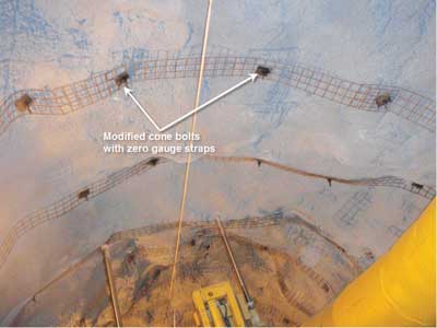
Figure 4—View of components used in a system to control burst-prone ground at Copper Cliff.
| Description | Peak load (kN) | Displacement limit (mm) | Energy absorption (kJ) |
| 19 mm resin-grouted rebar | 120–170 | 010–030 | 01–04 |
| 46 mm split set bolt (FS-46) | 090–140 | 080–200 | 05–15 |
| 16 mm modified cone bolt | 050–100 | 100–200 | 10–25 |
| 16 mm cable bolt | 160–240 | 020–040 | 02–06 |
| #4 gauge welded wire mesh | 034–042 | 150–225 | 3–6 per m2 |
| Shotcrete and welded wire mesh | 2 × mesh | < mesh | 3–5 × mesh* |
| * at displacements under 100–150 mm. | |||
| Table 1—Energy absorption and load-displacement characteristics of support elements (Kaiser et al., 1996). | |||
| Date | Magnitude | Orebody | Level (stope) | Remarks |
| 18-Feb-09 | 2.9 | 100 | 3710–3880 (9551) | No damage to mine openings |
| 30-Sep-10 | 1.9 | 900 | 3710–3880 (9281) | No damage to mine openings but 80–100 t of trap dyke material was sloughed into the open stope |
| 2-Oct-10 | 1.6 | 900 | 3710–3880 (9281) | No damage to mine openings |
| 4-Oct-10 | 1.4 | 900 | 3710–3880 (9281) | No damage to mine openings |
| 4-Oct-10 | 1.2 | 900 | 3710–3880 (9281) | No damage to mine openings |
| 5-Oct-10 | 1.9 | 900 | 3710–3880 (9281) | Some minor surface cracks in shotcrete |
| 15-Oct-10 | 2.3 | 900 | 3710–3880 (9281) | Minor damage to ground support system and some floor heaving |
| Table 2—Seismic events/rockbursts occurred while mining the stopes in the vicinity of the trap dyke in 100/900 OB. | ||||
Energy absorption capacity and load-displacement characteristics of the various ground support elements used in this rockburst-resistant support system are shown in Table 1.
Based on these energy absorption values, the total energy absorption capacity employed in the burst-prone ground conditions at Copper Cliff was calculated to be between 20 and 48 kJ per m2, based on the September 11 event.
Mining in the 100/900 orebodies at Copper Cliff resumed after installation of the burst-resistant system, and four stopes were mined out successfully without significant damage. However, following the resumption of mining, Copper Cliff again began to experience elevated seismic activity, particularly while mining the stopes surrounding the trap dyke. Several seismic events/rockbursts, ranging from 1.2 to 2.9 MN, occurred while mining the 9551 and 9281 stopes. The chronology of these seismic events/rockbursts is shown in Table 2.
It is interesting to note that no damage resulted from the 2.9-MN event on February 18, 2009, while mining the 9551 stope. The event was located 20 to 30 m from the top and bottom sills, respectively. This demonstrated that the rockburst-resistant support system installed after the 3.8-MN event had sufficient energy absorption capacity to withstand the impact of a 2.9-MN event.
During mining of the 9281 stope, the installed burst-resistant support system repeatedly experienced seismic event impacts and showed signs of negligible damage. Although it is difficult to assess the impact of previous seismic events in a quantitative manner, the ground control engineer determines if there are signs of support yielding based on personal observation and/or field instrumentation monitoring, if any. If support yielding has occurred, it may be determined prudent to install extra support to compensate for any potential loss in safety margin.
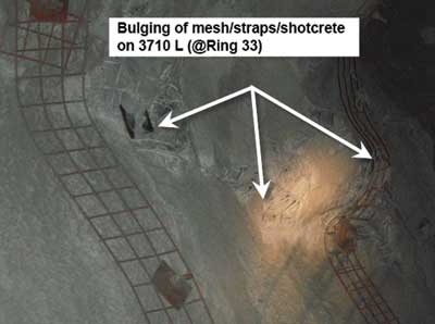
Figure 5—As shown here, the new system sustained only minor damage after repeated seismic events.
Although the burst-resistant support system was subjected to repeated seismic loading, it showed the first sign of damage only after a 2.3-MN seismic event in October 2010. However, the level of damage was insignificant (Figure 5).
Even though many seismic events occurred in the 100/900 orebodies while mining in the burst-prone ground conditions, no significant damage was associated with such events after introducing the burst-resistant support system at Copper Cliff. It was evident from underground observations that a well-designed dynamic support system will cope very well in the event of large and repeated seismic events, by sustaining the impact of dynamic loading with little or no damage to underground excavations and/or the installed ground support system. Four stopes were mined successfully without significant damage after introducing the burst-resistant support system.
D. Reddy Chinnasane is senior engineer-ground control, at Vale’s Copper Cliff mine. Mike Yao is principal engineer-ground control, MMTS Central Support, Vale Canada, Ontario Operations. This article is based on a paper presented at Deep Mining 2012, the sixth International Seminar on Deep and High Stress Mining, held in Perth, Australia, by the Australian Center for Geomechanics in March 2012. The ACG’s next conference on Deep and High Stress Mining will be held in Sudbury, Canada, September 16-18, 2014.