


Increase throughput by reducing maintenance downtime
By J. Wu, L.J.W. Graham and G. Short
There are two ways to protect against an aggressive force that is determined to wear down your defenses—build even stronger walls, or redirect it to minimize the damage. The traditional defense by the minerals industry against erosion of slurry flow equipment has been to use specialized wear-resistant materials, such as white iron with various hypereutectic alloys and carbides. An alternative approach is to design the geometry of slurry flow equipment to redirect particles to minimize the erosion impact. This fluid dynamics-based approach can be simple and effective for reducing erosion.
Experience suggests that wear is rarely uniform; localized erosion damage (“hot spots”) is common, as indicated in Figure 1. Removal of hot spots is beneficial for extending equipment life. This can be achieved by re-designing the velocity distribution such that the impact of particles and the resulting erosion is more evenly distributed.
 Figure 1—Industrial examples of erosion and wear that have been addressed: (a) an impeller, (b) screen, (c) orifice plate and (d) a rod (in a pipe).
Australia’s Commonwealth Scientific and Industrial Research Organization (CSIRO) has been conducting research under AMIRA International P931 “Multiphase Flow Erosion” projects since 2006, with sponsorship support from Alcoa Australia, BHP Billiton Worsley Alumina, Rio Tinto Alcan, Vale and Pentair Valves (Tyco Flow). AMIRA P931 projects focus on building knowledge and methods to predict the erosion service life of flow equipment and developing strategies through case studies to alter flow design to reduce erosion and extend equipment life. The project strategy has been one of developing a growing collection of flow design solutions based on fundamental studies. The emphasis has been on solving erosion problems using the principles of the underlying multiphase fluid dynamics, rather than modifying materials of construction.
 Figure 2—Erosion on material surface for ductile (Al) and brittle materials (Al2O3) as a function of particle impact angle at a given velocity.
This approach is possible as erosion (rate) is a function of particle velocity and particle impingement angle for any given material. Erosion increases with velocity to a power of approximately 2–3 depending on the material properties. The effect of the angle at which particles impact on to the surface is shown in Figure 2, and is well known in erosion-science literature.
Several common fluid dynamic mechanisms responsible for severe erosion attacks have been identified and their solutions demonstrated during the P931 projects. These mechanisms are indicators of the effect of both velocity and particle impact angle. These include erosion by vortices, by flashing and by various non-uniform flows. Erosion attack under vortex flow has been found to produce consistently more damage compared with “normal impact erosion” on, for example, a pipe elbow or the sample cylinder. It was found that vortices tend to increase the erosion by increased particulate impact angle and increased number of solids impact hits due to trapping of solids by the vortices. A geometric feedback effect is also in play: damaged “dips” would lead to enhanced vortex strength, thus higher swirling velocities, leading to more damage to the surface and with a greatly amplified damage effect.
 Figure 3—Erosion attack due to horseshoe vortices in a cylinder-in-pipe protrusion configuration: (a) cylinder in slurry pipe configuration and erosion damage after; (b) a CSIRO design achieved approximately four times reduction in erosion.
An example is shown in Figure 3(a), where a cylinder placed in a slurry pipe flow increased erosion damage due to formation of horseshoe vortices. Measured erosion damage here was found to be approximately three to five times higher than a direct impact on the cylinder and approximately 100 times more than that on the pipe wall if the cylinder was removed. This problem has now been solved by a design change (confidential to sponsors of the AMIRA International P931 projects), resulting in an approximate 80% reduction in maximum erosion damage. This comparison between the original design and effect of the modified design by CSIRO design is shown in Figure 3(b).
The fluid dynamics design approach has been successfully used in the P931 projects. All new designs developed and tested successfully have been entered into the Erosion Knowledge Base, an online reference source for sponsors. The Erosion Knowledge Base currently contains examples of basic solutions for reducing destructive erosion phenomena such as that caused by vortices in pipe tee-sections, erosions in pipe bends, at impeller blades, at pipe joints, in valves and severe erosion due to slurry boiling during flashing in parts of process pipework. This information provides sponsoring companies with insights into erosion problems encountered within their operations and offers possible solutions, or provides a sound starting point for additional investigations.
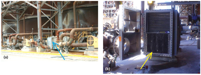 Figure 4—Design change dramatically improved wear life of Barriquand coolers at Rio Tinto’s Yarwun alumina refinery in Queensland, Australia: (a) Barriquand coolers in operation at Yarwun; (b) perforated plate insert at inlet of the cooler.
Since starting in 2006, many full-scale design changes have been made based on the knowledge developed in P931 projects. This includes a design change to solve the erosion of cooling plates in heat exchangers at Rio Tinto Alcan’s Yarwun alumina refinery in Queensland in 2008. Bauxite is the ore used to produce alumina in the Bayer process. In this process alumina is dissolved out of bauxite and then crystalized via cooling, producing a pure form of hydrated alumina. This hydrated alumina is very abrasive and can cause severe erosion as it passes through heat exchangers, which contain multiple cooling plates. CSIRO developed a design to make the slurry flow more uniformly by inserting a type of perforated plate to homogenize the flow. This eliminated the peak erosion hot spots and minimized damage to the cooling plates. The benefits from implementing that single piece of advice have been dramatic. The feedback from the end user was that “the life expectancy of cooling plates has been extended from a few days to more than 12 months, representing a major saving in the maintenance costs. The biggest reward, however, is minimizing plant shutdowns and maximizing production.”
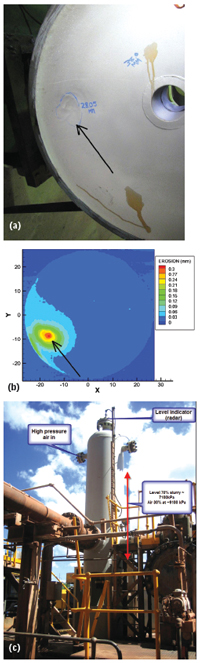 Figure 5—Design change to solve an erosion problem in the bottom of a pump accumulator at Rio Tinto Alcan Yarwun: (a) erosion, (b) laboratory measurement confirmed vortex erosion attack, (c) design change developed in the laboratory that has been applied in full-scale.
Similarly, a design change was developed through laboratory modeling to solve a “holing” wear problem on the bottom of a pressure vessel downstream of a PD pump. Figure 5(a) shows the wear damage, (b) measurements in laboratory led to a development of a design change to solve the problem, (c) implemented in the full-scale in 2012. Operating experience so far suggests that regular welding repair has now been avoided, reducing downtime and maintenance cost. Officials at Rio Tinto Alcan–Yarwun said, “The work to change the flow characteristics of the fluid entering the vessel will more than double the life cycle of the vessel. This will reduce the maintenance costs by $1.3 million over four years.”
For sponsors with CFD modeling capability, more accurate erosion predictions have been made possible through tests to quantify the erosion distribution of flow geometries relevant to minerals plants under controlled slurry flow conditions. The example in Figure 5(b) shows erosion distribution over a disc, after experiencing erosion from a vortex flow. The tests were conducted using a slurry erosion test facility and surface profiling system (Figure 6(a) and (b)). A novel cylinder erosion test database was developed to allow rapid estimation of the erosion in complex geometries in full-scale plant conditions.
 Figure 6—Slurry flow erosion test facility at CSIRO: (a) test section being installed, (b) Coordinate Measurement Machine to measure erosion distribution accurately (~5μm).
It is planned to continue this AMIRA program in a new P931B project for the next three years. Sponsorship is now open. For technical questions, contact Jie.Wu@csiro.au. To inquire about joining this program, contact Gray.Bailey@amirainternational.com.
Jie Wu, L.J.W. Graham and G. Short are associated with the CSIRO Minerals Resources Flagship in Advanced Processing Technologies.


