


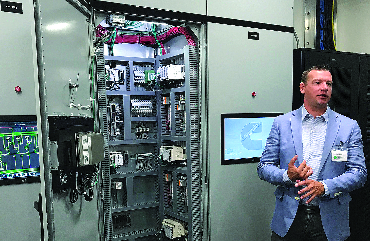
Corey Bergendahl, engineering manager for the PIC explains, how the lab lets him and his team test various microgrid configurations.
New microgrid testing lab can determine how well integrated power sources will work with varying load profiles
By Steve Fiscor, Editor-in-Chief
Cummins Inc. recently celebrated the grand opening of a new microgrid lab called the Power Integration Center (PIC) at their Power Systems facility in Fridley, Minnesota. The PIC is a state-of-the-art facility that allows for the configuration, integration, and testing of power system technologies, including diesel and natural gas generator sets, photovoltaic (PV) solar panels, battery storage systems, fuel cells, transfer switches, switchgear, and system-level controls.
“The PIC is the realization of a significant investment in engineering technology and innovation that will impact how companies use and build power systems to meet sustainability goals for a greener future,” said Gary Johansen, vice president of power systems engineering and PIC project sponsor.
Using the PIC, Cummins engineers can experiment with multiple potential power system solutions directly. It allows them to save time and money, and provides the ability to optimize a power system for any project. “With this center, we’ll be able to enhance our offerings throughout the project lifecycle,” said Satish Jayaram, IDEA program office leader and PIC project sponsor. “We will reduce the cost and time it takes to test and validate solutions.”
If a mining company was planning to open a greenfield site in a remote region, it would likely need to establish its own utility infrastructure or microgrid. To build the microgrid, the mining company would need to know the projected electrical load profiles for the project and whether the climate could support solar and wind. The Cummins engineers working at the PIC lab could then calculate the operation’s power drain, simulate the load profile, create the control room, and test the microgrid. Before the mining company invests $100 million, it would know whether its microgrid would work as planned.
Establishing the PIC
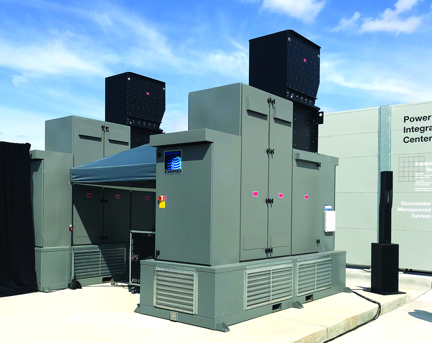
The 1,900 m2 PIC lab space includes an outdoor test area, main switchgear room, electrical mezzanine, and an engineering control room. Many different types of assets such as generator sets, energy storage systems, fuel cells, and inverters can be brought in for testing in a wide variety of possible microgrid configurations. The outdoor test area includes five 500-kW test pads and two 2,000-kW test pads, which can be connected as sources or loads. Two load banks allow for scenarios to be run using real load profile data from the mines, at up to 0.8 leading or lagging power factor.
Three indoor switchgear line-ups connect the different assets in the lab, and provide a tie-in for the lab’s utility connection. A 500-kW permanently installed roof-mounted photovoltaic (PV) system is connected to the lab, as well as PV and energy storage simulators for testing various types of inverters. The engineering control room includes workstations where technicians can access all elements of the microgrid system, and work collaboratively with customers and technical partners.
Concrete pads in an outdoor area allow the Cummins engineers to use real generator sets (gensets) burning real fuel (diesel, natural gas, hydrogen, etc.) that has been plumbed to all the pads. Inputs for battery, solar and wind are replicated from algorithms provided by the suppliers. Once they know the expected climate conditions and the storage and discharge capabilities, the algos tell the system how much power these sources will provide to the microgrid.
The two load banks were a massive investment for the PIC program, and they have given the engineers the ability to move from theoretical testing on paper to actual testing. The fully-programmable, 500-kW load banks replicate load profiles for the system. The engineers upload the mine’s load profile, like the power requirements for the mill, the fans, the offices and shops, etc. The load bank doesn’t know if it’s sitting in the middle of Africa or at a test facility in Minnesota.

The electrical mezzanine connects sources and loads, and allows the engineers to test various inverters.
Put the System to Work
Integration is the keyword in the phrase Power Integration Center, explained Corey Bergendahl, engineering manager for the PIC. “Previously, we used individual test cells and they are really good for testing one thing, one genset, one transfer switch, one fuel cell, etc., but it’s really difficult to tie those test cells together, almost impossible, in the way that they were constructed,” Bergendahl said. “When we tried to do that, we would set equipment up in a parking lot and cable them together and that amounted to a custom one-off kind of test. During the final phase of commissioning, especially when we’re working with emerging technologies, it’s usually not just a couple of days of checking the boxes and everything just works well.” He was a commissioning engineer for 10 years and knows that’s not usually the case.
The PIC facility provides a dedicated lab where Cummins can test a scaled power system. “It gives us the freedom to build the microgrid that we want to test and then actually test that with whatever type of load that we want,” Bergendahl said. “If we want to turn power off 13 times and restart it on the same day — no problem. Doing that at a mine site would be really inconvenient.”
Two 500-kW load banks allow for scenarios to be run using real load profile data from the mines.
Microgrids are sources, loads, connections and controls. “With the PIC, we have a testing system that is flexible and dynamic,” Bergendahl said. “We have the infrastructure to create many different electrical topologies, and we have the flexibility to move those assets around within those topologies, which is really cool.” It’s also really cool that they can control all of that from a control room rather than running around changing cable connections.
This system has important safety considerations as well. “When connecting and reconnecting anything at this kind of power scale, you need to test the cable and the connections,” Bergendahl said. “You must also test for synchronization and phasing when connecting multiple sources. With the infrastructure that we put in place, we go through that commissioning one time and we’re confident that its connected correctly. We have that protection in place all the time, and then we layer other controls on top of that to do our testing.”
The PIC engineers can configure the physical power system and they can also manipulate the network topology. “Controls are a big part of microgrids,” Bergendahl said. “We can evaluate the tradeoffs between different types of network configurations, such as a ring network or a redundant star. We want to be able to play with all that stuff too. We can examine different cyber security protection options for the network. This is a facility that serves no critical loads, so we can bring in disruptive elements into the network in a safe way and see what impact that has on the actual power systems.”
The electrical system for a haul truck could be considered a microgrid. It has a power source, loads and a distribution network. As haul trucks transition from diesel-electric to the next generation, whether it be battery, trolley-battery, hydrogen, etc., the inverter technology will also change. This lab could be used for inverter validation tests.

Three indoor switchgear line-ups connect the different assets in the lab, and provide a tie-in for the lab’s utility connection.
Practical Applications
Bergendahl ran a demonstration of a single transfer pair with solar and battery storage for E&MJ. “We have a utility source, two generators, a generator main breaker and a utility main breaker, that utility main-generator main combination makes up the transfer pair,” Bergendahl said. “This demo also has a solar array and battery storage. It also has two loads.”
The object of the test was to control how much power the user is purchasing from the utility. He established a 100-kW set point for the utility import. “We will put the system in transition mode, utility power control mode, and our target is 100 kW at the utility breaker,” Bergendahl said. “We have 50 kW of load on the system. We want the utility to be at 100kW so will ask the utility to supply more power.”
Utility power is relatively cheap and the system uses the excess power to charge the battery. The sun begins to rise and the solar array starts to produce power. The solar array produces 25 kW, while the load remains at 50 kW, so 75 kW is used to charge the battery.
The microgrid is running as it should and the utility feed reaches 100 kW. The utility provides whatever is demanded of it, and the swing resource is the battery storage system. “We’re sending a command to the battery system to tell it how much to charge or discharge to maintain that 100 kW,” Bergendahl explained.
Bergendahl changes the load to show how the system responds. “Now we have 200 kW of total system load, and we’re getting 75 kW of battery, 25 kW of solar, and 100 kW utility,” Bergendahl said. “A big load step occurs, the utility spikes and then it drops, and the reason why it’s dropping down to that 100 kW is that we’re very cleanly ramping up that battery system. Cummins Control is monitoring all the power in the system and sending the commands to the battery system.”
That’s the value proposition that Cummins brings to the table. “Oftentimes when industrial facilities are trying to integrate components, the individual components suppliers say that they can serve as the master control for the system, but the reality is that it can’t be done effectively from the component level,” Bergendahl said. “There is a control scheme inside each of those local assets, and it has to be controlled by an entity that has the logic and interface with all of the different inputs and that’s what we are seeing here.”
To finish up the demo, Bergendahl induces a utility failure. Everything goes dark, the solar drops off and the battery is depleted. The gensets fire up. They come online in 10 seconds. “Load No. 1 was deemed noncritical, so it is not added immediately,” Bergendahl said. “Now we’re seeking a different target. These gensets are most fuel-efficient when running at 60% of their rated load and the system knows it. They are 100-kW units, so it will try get 60 kW from each genset, or 120 kW total. We have got 50 kW of load, so now that means that we’re actually using the generators to charge the battery system.”
A mine might have different priorities. It may want to run the least number of gensets possible, so after they started and became stable, the system could shut one of them down. Or maybe the load is low enough to run off battery storage and the operation can shut both of them down until utility power is restored. There are numerous possibilities of how the microgrid can operate depending on the load, Bergendahl explained.

The visual interface for the single-pair transfer demo shows (upper left to right) utility power, solar, battery storage and two gensets. The lower section shows the load.
Power costs could be layered on top to demonstrate the economic gain and losses. “We come from the backup power market, which is high resiliency, high mobility and control,” Bergendhal said. “Complex power systems are our area
of expertise. We know what we can provide and we look to the customer to tell us the right level, such as the 100-kW set point. Then based on all these other external factors, models using AI and live forecasts might determine the facility should run at 150 kW for the next two hours and then after that the power will be more expensive, so the load should drop to 20 kW. We can put all of that into the controller and it will act on it.”
The utility source in the demo comes back online and the system performs a closed transition return. “In this case, the generator bus is synchronized with the utility bus,” Bergendahl said. “The renewables and battery remain online. We will ramp down the output of the generators. Ramp up the utility. The gensets disconnect and turn off. The non-critical load gets re-connected and we return to the steady state prior to the utility drop.”
Keeping the solar and battery online during the transition is not a trivial decision as they have inverters that are programmed to be sensitive to frequency and voltage swings, Bergendahl explained. “If you get a big frequency change or voltage swing, they will turn off, try to reconnect and come back onto the system,” Bergendahl said. “Some customers would rather not risk those systems. They would choose to shut them down during the transition and bring them back online after the systems have stabilized if they have the ability to do that. We can do that. We can do some testing to quantify what that would mean. We could determine whether turning the solar off for 5 minutes during a closed transition return is really going to make a difference. In other off-grid applications or areas with unreliable grid service, taking the solar or batteries offline for long periods might not make sense.”
This service from Cummins gives mining companies a chance to lean on someone else to solve the power side of the equation quickly, efficiently and cost-effectively. And, it can provide the confidence that the microgrid will work as designed and what will happen during extreme situations.


