


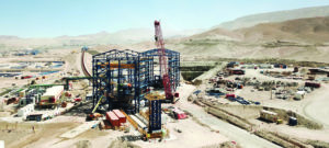
A construction photo shows the transfer building where Chuquicamata’s 11,000-mt/h conveyor system, which travels a 6.4-km ramp from the underground ore storage bins, discharges on to another conveyor that transports the ore to a processing facility 5 km away.
Modern conveyors systems can be engineered for greater capacities, low maintenance and high availability
By Steve Fiscor, Editor-in-Chief
For material handling, few systems can compete with conveyors, especially over long distances. Those long distances on grade or uphill, however, require more power and stronger belting. They also usually involve a transition such as a curve or a transfer point, which introduces another set of variables and more costs.
Conveyors also require a lot of moving parts, including motors, drives, pulleys, and idlers. These moving parts along with the chutes in the transfer points require maintenance. To keep the availability high on these systems, they must be designed with maintenance in mind.
When a mine makes this type of major capital investment, it expects high levels of availability. Usually, these conveyors are the primary means of ore transport and, when they go down, the entire operation goes down. To protect the investment and maintain production, they also must be designed with a relatively high safety factor.
Conveyor systems continue to evolve. Previous systems were a series of flights with each flight traveling in a straight line. They were limited by elevation changes and the tensile strength of the belting. Over the years, the engineers that design these systems have learned how to install curves and increase the amount of power the drives can input into the system.

Installed in a drift that extends 6,400 m to the surface, the inclined conveyors overcome an elevation of 950 m.
Building the World’s Most Powerful Conveyor
In 2019, Corporación Nacional del Cobre de Chile (Codelco) converted its Chuquicamata mine, one of the largest open-pit copper mines in the world, to an underground operation. The state-owned company selected TAKRAF to supply the principal ore transportation system that move crushed copper ore from underground storage bins to a mineral processing facility on the surface.
“The system called for no redundancies, which meant that for this project, high system availability, minimal system wear and easy maintenance of components were all decisive factors,” said Mario Dilefeld, head of belt conveyor systems for TAKRAF GmbH, who has a doctor in engineering.
The scope of the Chuquicamata Underground Project (Chuqui UG) called for:
• Removal of crushed ore from 60 m high underground storage bins with a conveying capacity of 11,000 metric tons per hour (mt/h);
• Transportation to the surface with a minimum number of transfer points;
• Conveying the ore from the underground tunnel exit to the processing plant; and
• Ensuring high-system availability, minimal system wear and easy maintenance of all components.
The conveying network begins at the underground ore storage discharge. Two ore storage bins measuring 6 m in diameter and 60 m in height control the flow of mined material onto the conveyors. Feeder conveyors move ore from the storage bins to the main conveyors. “As with any belt feeder, the contour of the material to be conveyed is specified by a shear gate and the flow of discharged material is defined by varying the conveying speed,” Dilefeld said.
Two conventional trough conveyors connect the feeder conveyors with the loading point of the inclined conveyor around 900 m away. Installed in a drift that extends 6,400 m to the surface, the inclined conveyors overcome an elevation of 950 m. “Each underground transfer point along the tunnel required an underground chamber with a crane for maintenance work, power supply, transformers, and electrical and mechanical drive technologies, with adapted ventilation and suitable access paths,” Dilefeld said.
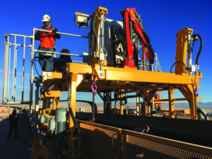
To replace idlers, a specially designed maintenance vehicle travels along the conveyor path.
To minimize the number of transfer points, the inclined conveyor section was successfully developed employing just two flights. “To achieve this feat, it was necessary to use newly developed components that redefine the performance limits of belt conveyor technology,” Dilefeld said. “ST10,000 quality conveyor belts were used for the first time underground. Operating belt safety ratings of S=5 required belt connections with a reference fatigue strength of more than 50%. This value was proven on a belt test rig at the University of Hanover in Germany. Once again, new dimensions were achieved — this time in terms of installed drive power — with 10 megawatts (MW) of installed drive power per drive pulley and 20 MW per conveyor.”
In cooperation with the drive motor manufacturer, ABB, TAKRAF engineers developed a drivetrain consisting of a 5-MW synchronous motor, a membrane coupling to connect the pulley shaft and rotor shaft and a drive pulley.
The drive pulley had the following specifications:
• Simple alignment and motor air gap adjustment during installation of the drive;
• Simple readjustment in the event of motor air gap deviations from the setpoint (e.g., after settling);
• Complete and fully assembled factory-tested motors on site (no motor assembly in a dusty environment); and
• Simple separation of the connection between the drive pulley and motor to ensure continued operation of the system for the short term with a reduced number of drive motors.
Maintaining the air gap between the rotor and stator was a crucial requirement for the operation of the motors, Dilefeld explained. The air gap, which is 14 mm, must only be allowed to deviate from the setpoint within small tolerances. “Deviations in the air gap reduce the efficiency of the motor, and if rotor and stator were to make contact with each other, this would result in damage to the motor,” Dilefeld said. “The air gap itself is continuously monitored during operation. If deformations and/or subsidence in the steel structure or in the motor foundations lead to a deviation in the air gap setpoint, the stator must be realigned. To simplify this process, the spacing between the rotor and stator at the non-driven end of the motor was fixed by a support bearing.”

The overland conveyor passes over infrastructure that has accumulated over 100 years.
The membrane coupling compensates for the deformation of the pulley shaft caused by belt tension, Dilefeld, explained. “The adjustable motor frame facilitates alignment of the motor during installation and ensures simple realignment if necessary,” Dilefeld said. “Eccentrics and spindles allow the stator to be adjusted in all directions. Should a motor fail, it can be quickly moved into a disabled position by opening the membrane coupling and adjusting the spindles. The system can then continue to operate only with reduced power.”
The conveyor from the underground tunnel discharges on to an overland at transfer station. That overland conveyor delivers ore to the mineral processing plant 5 km away.
The landscape surrounding the processing plant has been shaped by more than 100 years of mining at Chuquicamata. In addition to the various processing systems, waste heaps, railroad tracks, roads, pipelines and buildings scar the landscape. The challenge for the new conveyor system was to design a system that took into consideration this landscape for its entire length.
The overland was a continuous single-flight conveyor developed with the following parameters:
• Distance of 5,330 m between the material loading point and material discharge with a difference in height of 287 m;
• Horizontal curves with tight radii (1,600 m to 2,300 m) on more than 60% of the conveyor length; and
• Approximately 50% of the conveyor length on elevated structure with variable lengths adapted to local conditions for foundations positioning and with support intervals of up to 96 m.
The conveyor design again revolved around ensuring high system availability, minimal system wear and easy maintenance of components. All loading points along the conveyor route were optimized in order to reduce conveyor belt wear. The arrangement of the rock boxes and grizzlies was verified with simulations using the Discrete Element Method (DEM).
Specially designed transfer chutes allow wear plates to be replaced quickly and easily. To replace idlers, a specially designed TAKRAF maintenance vehicle travels along the conveyor path, Dilefeld explained. “It can lift the conveyor and replace worn idlers to safely and efficiently,” he said. “At the material discharge point, a bunker building performs a limited material storage function. Two feeder conveyors remove the material and feed it to the processing plants.”
Three 5-MW direct-drive motors drive this conveyor, with a ST6,800 conveyor belt with a belt safety of S=5.1 being used, Dilefeld said. Vibration behavior of the belt during start up and braking was analyzed across all operating conditions using dynamic belt calculations.
System parameters such as a ST10,000 conveyor belt and 20-MW drive power per conveyor redefine the limits of belt conveyor technology, Dilefeld said. This made it possible to achieve the goal of reducing the number of underground transfer points, thereby justifying the use of these components.
High system availability, minimal system wear and easy maintenance of components were essential criteria when designing this system. Numerous innovations that were implemented for the first time. Six patents were awarded on this project, which resulted in a modern, powerful and environmentally friendly conveyor system.
Designing Chuqui UG’s Drives
ABB provided the engineering design, gearless conveyor drives, electrical equipment for power supply, energy distribution and automation for the Chuqui UG conveyor systems. The three principal 11,000-mt/h conveyors feature gearless conveyor drives equipped with large ABB AC synchronous motors with a rated power of 5 MW each, resulting in a motor shaft torque of about 900 kNm. It is also the first transportation system in the world to employ the ST10000 steel cable belt technology on an uphill drift (ramp) conveyor.

The overland conveyor’s discharge at the mineral processing facility employs four 5-MW gearless drives (inset).
“This mega project achieves a number of firsts, from the system’s installed drive power to the application of the ST10000 conveyor belt,” said Marc Hollinger, TAKRAF project manager. “This was a complex project of the highest magnitude demanding global cooperation between internal and external parties.”
“This is a new milestone in underground applications for continuous mining. It is the highest drive power ever installed on a conveyor and uses a wide range of features for data acquisition, equipment assessment and process optimization,” said Ulf Richter, global product manager for belt conveyor systems at ABB. “In piloting this gearless drive application with TAKRAF, we have overcome tremendous technical and logistical challenges due to underground situations, elevation change and capacity requirements.”
ABB liquid-cooled MV voltage-source frequency converters, together with large synchronous motors, deliver a decrease in active and reactive power consumption. This is highly energy efficient, and without additional network filters.
ABB’s Mining Conveyor Control Program (MCCP) ensures smooth belt operation and safe synchronization between high-power motors and high-power hydraulic brakes, necessary for secure operation of steep uphill conveyors. The drive systems also work without mechanical backstops.
A novel embedding concept, developed jointly by TAKRAF and ABB, enables straightforward installation and alignment of the gearless conveyor drive motors, saving installation time and longer deployment of maintenance teams. This was considered a major benefit compared to existing gearless conveyor drives in cantilevered construction. The concept also meant motors were 100% factory assembled and tested. They can also be mechanically disconnected from the drive pulley quickly so operations can continue if drive failure occurs. The total installed drive power for the entire system, including multiple feeder conveyors, totals 58 MW, of which there are 11 5-MW gearless synchronous motors. The new underground project is expected to extend operations at the Chuquicamata mine for the next 40 years.
PPI Supplies Hardware to Yukon

A Yukon gold mine recently installs this overland conveyor with PPI structure and hardware.
During June of 2018, PPI was awarded a contract to supply the pulleys and idlers for a mining project in Canada’s Yukon Territory. The heap-leach gold mine is the most advanced in the region and is developing toward becoming the largest gold mine in Yukon’s history. “Our customer supplied the material handling system to the mine owner,” said Nick Phillips, product sales manager, PPI. “The extent of the project included nine conveyors and three feeders, ranging in belt widths from 42- to 72-in. wide.”
This project required collaboration from various departments within the U.S. and Canada to make this opportunity a success. The contract scope included a large number of pulley assemblies produced at PPI Canada, as well as a large number of idlers and structural components from PPI U.S. Over the course of several months, 63 pulleys with shafts, bearings and take-up frames, were manufactured and shipped to the mine site. During this time period, approximately 20 truckloads of idlers and structures shipped from PPI Corning and PPI Lenox to the mine site.
For long, flat overland conveyors, PPI produces a stand that works well. “We can produce the C channel, rail sections and stands, and we can supply those at a competitive price,” Phillips said. “It’s great way to build an overland. When the material arrives at the mine site, the crews just bolt it together.” The mine is currently using the system to place ore on the leach pads.
A Transfer Unto Itself

RBL-REI inserts a transfer point in one continuous conveyor. Traditionally one conveyor discharges on to another at a transfer point.
RBL-REI has recently commissioned a belt deviation system for a Polish mining company, which allows one belt to change direction without motorization. Due to the narrow corridor available between the quarry and the plant, RBL-REI was asked to engineer the conveyor system. Ordinarily, that would include a transfer point and two separate overland conveyors between the origin and the destination. To optimize the project capital expends and coordinate starting and stopping times between the two overland conveyors, RBL-REI designed a single flight system — meaning the same belt is working upstream and downstream from the transfer point. A belt deviation system without motorization was specially developed for this project to unify the two sections. In addition to eliminating the costs of the drives and a substation, the system also avoids the problems of chute clogging with sticky material.


