


By Adam Willwerth
A simple method now allows VFD-induced electrical bearing damage to be prevented—not just repaired
Variable frequency drives (VFDs, also known as inverters) can save 30% or more in energy costs. Because of this, they have been cited as a key technology for those wishing to make their processing plants, HVAC systems and other equipment more energy-efficient. Unfortunately, whether used to control a motor’s speed or torque, VFDs often induce voltages and currents that can damage bearings.
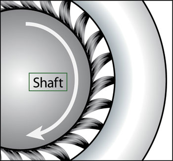
Figure 1: The best grounding rings are lined with flexible, conductive microfibers that completely surround the motor shaft.
In fact, the costly repair or replacement of failed motor bearings can wipe out any savings a VFD yields and severely diminish the reliability of an entire system.
Until all motors are designed with built-in bearing protection, plant maintenance personnel and motor repair shops will continue to replace damaged bearings. But if a motor’s bearing problem is fixed properly and proper mitigation installed, it only has to be done once. Better yet, the latest diagnostic techniques (vibration analysis, thermography, shaft-voltage testing, etc.) can prevent electrical bearing damage or nip it in the bud. Whether working on a brand new motor or one already in service, an informed technician can now protect bearings during the life of the motor. This is what we mean by “best practices.”
Damage
The high switching frequencies of today’s VFDs produce parasitic capacitance between a motor’s stator and rotor. By now, it is widely understood that, once the resulting shaft voltages overcome the dielectric properties of bearing grease, they discharge along the path of least resistance—typically through the bearings.

Figure 2: A channel locks the ring’s conductive microfibers in place around the motor shaft and helps protect them from dirt, oil and other contaminants.
These discharges are so frequent that they create millions of tiny fusion craters. Before long, the entire bearing race wall can become marked with countless pits known as frosting. A phenomenon known as fluting may occur as well, shaping the frosting into washboard-like ridges across the bearing race. This causes noise, vibration, increased friction and catastrophic bearing failure.
As the bearings degrade, the tiny metal particles blasted from the fusion craters intensify friction and abrasion, heat up the bearings, and burn the contaminated grease. Too often, the end result is bearing failure and costly, unplanned downtime.
Failure rates vary widely, but evidence suggests that a significant portion of failures occur only three to 12 months after system startup. Because many of today’s motors have sealed bearings to keep out dirt and other contaminants, electrical damage has become the most common cause of bearing failure in AC motors with VFDs.
Inspect, Then Protect
Cutting and carefully inspecting the bearings of motors needing repair will often provide information that can be used to prevent a recurrence of the problem.
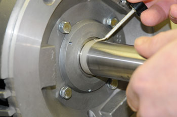
Figure 3: Prior to installation of a grounding ring, the motor shaft must be cleaned down to bare metal, free of any nonconductive material. Conductivity can be further enhanced by coating the part of the shaft that will contact the ring with colloidal silver.
If inspection of the old bearing indicates electrical damage, the most reliable and cost-effective way to protect replacement bearings is to install a modern shaft grounding ring. Unlike older single-point contact brushes, these rings completely surround a motor’s shaft with contact points. Conductive microfibers should line the ring’s entire inner circumference, boosting the electron transfer rate (Figures 1 and 2). A properly installed ring provides a very low impedance path from shaft to frame, safely bleeding off damaging voltages to ground and bypassing the motor’s bearings entirely. And because the microfibers work with little or no contact, they do not clog up and wear out like conventional grounding brushes.
A growing number of forward-looking motor manufacturers have recently added a factory-installed shaft grounding ring as a standard or optional feature on certain models, but they are still exceptions to the rule. Many industrial supply houses and distributors of motors and bearings sell grounding rings that can be installed on new, refurbished or in-service motors.
Tips for Ring Installation
To maximize a grounding ring’s effectiveness, all electrical paths must be conductive. Paint on the motor’s faceplate must be removed. Likewise, the motor’s shaft must be cleaned down to bare metal. Even after scrubbing with emery cloth, wiping the shaft with a non-petroleum-based solvent will remove unseen residues. After cleaning, the conductivity of the shaft should be checked with an ohm meter. If the reading at the section that will contact the ring’s microfibers is higher than two ohms, the shaft should be cleaned again.
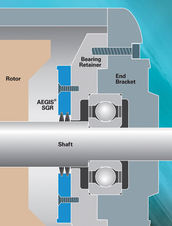 Figure 4: Internal installation of the grounding ring provides extra protection from dust, dirt and other contaminants in severe-duty applications.
A grounding ring should never operate over a shaft keyway, which has sharp edges and could reduce conductivity. On some motors, the dimensions of the spacer and mounting screws can sometimes be adjusted/changed to avoid a keyway. If this is not feasible, the portion of the keyway that will contact the ring’s microfibers should be filled with epoxy putty.
Conductivity should be further enhanced by lightly but evenly coating with colloidal silver any portion of the shaft that will contact the ring’s microfibers. This will also help retard corrosion (Figure 3).
Threadlocking gels and liquids other than conductive epoxy are not recommended for the screws that mount the ring to the motor, as they might compromise the conductive path to ground.
The ring should be centered on the motor shaft so that its microfibers contact the shaft evenly.
When mounting the ring externally to an end bracket, split rings designed to slip around an in-service motor’s shaft instead of over its end simplify installation.
After installation, testing with an ohm meter is again recommended. The best method is to place one probe on the ring and one on the motor frame. (The motor and drive must be grounded to common-earth ground in accordance with applicable standards.)
Variations Suitable for Mining
For environments where the motor will be exposed to excessive amounts of dirt, dust or other debris, it may be necessary to protect the ring’s fibers with an O-ring or V-slinger. Bearing isolators with built-in circumferential grounding rings are also available. For severe-duty environments such as mining, however, mounting the shaft grounding ring inside the motor provides the best protection from contamination (Figure 4). Using conductive epoxy or screws, the ring can be mounted directly to a bearing retainer (Figure 5). An additional machined spacer will keep the ring away from the bearing grease cavity. Metal-to-metal contact is still essential, so the bearing retainer must be free of any coatings or other nonconductive material where it will touch the ring.
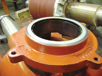 Figure 5: For internal installation, the grounding ring is often mounted in a bearing retainer.
For horizontally or vertically mounted motors with horsepower of 100 (75 kW) or less and single-row radial ball bearings on both ends, a shaft grounding ring can be installed on either end. For horizontally mounted motors with horsepower greater than 100 and single-row radial ball bearings on both ends, the bearing housing at the nondrive end must be electrically isolated to disrupt circulating currents. Options for achieving such isolation include insulated sleeves, nonconductive coatings, ceramic bearings or hybrid bearings. The grounding ring should be installed at the drive end.
For any motor in which the bearings at both ends are already insulated, the drive end is preferred for installation of a grounding ring, to protect bearings in attached equipment such as a gearbox, pump, fan or encoder.
For any motor with cylindrical roller, Babbitt or sleeve bearings, the end with such bearings should be electrically isolated, and the grounding ring should be installed at the opposite end.
Testing and Analysis
Measuring shaft voltage on a VFD-driven motor provides valuable information for determining whether there is a risk of electrical bearing damage. The best time to take such measurements is during the start-up of a new or recently repaired motor. Every motor has its own unique parameters. Combined with vibration analysis, thermography or other diagnostic services, results (including saved oscilloscope-screen images) can be presented in a report to the supervisor. Results should then be used in developing preventive and predictive maintenance programs.
Shaft voltages are easily measured (using appropriate safety procedures) by touching an oscilloscope probe to the shaft while the motor is running. The best probe will have a tip of high-density conductive microfibers to ensure continuous contact with the rotating shaft. A portable oscilloscope with a bandwidth of at least 100 MHz should deliver accurate waveform measurements. Probe/oscilloscope kits are available.
Just as shaft voltage measurements can show that a motor’s bearings are in danger of electrical damage, they can also confirm that a shaft grounding ring is working. If a proven ring has been properly installed, typical discharge voltage peaks should be less than 10 volts.
In summary, routine inspection, testing, and analysis can provide advance warning, and when bearings fail, proper repair practices can fix the problem for good. Motor shaft grounding rings such as AEGIS® bearing protection rings can be installed during motor repairs or on new motors before they are put into service.
Adam Willwerth is the sales and marketing manager for Electro Static Technology. For a 36-page handbook on the practices summarized in the above article, contact Electro Static Technology, 31 Winterbrook Road, Mechanic Falls, ME 04256-5724, Tel: (207) 998-5140, Fax: (207) 998-5143, www.est-aegis.com/bearing.


