


By Jie Wu, Steven Wang, Bon Nguyen, Tom Connor, Marjavaara Daniel and Eriksson Ola
Large-scale tanks with working volumes in the range of 1,000-5,000 m3 per tank are used in the minerals processing industry to provide feed storage and various continuous hydrometallurgical processes such as leaching (digestion), precipitation, adsorption, oxidation, tailings washing and neutralization. Typically, single or multiple impellers with vertical baffles inside these tanks are used to provide solids suspension and mixing. In some applications, draft tube agitator or air-lifting pipes are used.
It is not uncommon that slurry tanks experience reliability issues, which lead to maintenance shutdowns. Sedimentation accumulation due to solids settling on the tank bottom can result in agitator bogging; and scale formation often causes increased sedimentation buildup, due to solids being “glued” together into large lumps by precipitates. Cleanup of sedimentation and scale lumps requires considerable tank offline time. Other issues, including erosive wear and mechanical failure, also reduce operational reliability of slurry tanks. These reliability problems lead to lost production and increased labor cost.
The minerals industry is facing the dual challenges of prolonged lower commodity prices and a long-term trend of decreasing ore grades. It is imperative to improve plant productivity and reduce operating costs. The authors have found there are significant improvement opportunities available through innovation in the area of slurry tank agitation technology—typically requiring only simple design changes at a relatively low cost. This article introduces our experience in improving off-bottom solids suspension and mixing to dramatically increase plant productivity by applying CSIRO’s swirl flow agitation technology.
The Basics
To illustrate the approach, it is useful to introduce an empirical coefficient S to quantify “status of suspension” at the tank bottom: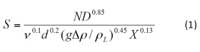
where N is the agitator (rev/s), ρL is the liquid density (kg/m3), Δρ is the density difference between solid and liquid (kg/m3), d is the solid particle diameter (m), D is the impeller diameter (m), ν is the kinematic viscosity of liquid (m2/s), and X is the solids loading (weight of solids/weight of liquid × 100). The S coefficient is based on the well-established Zwietering correlation1, which essentially is an empirical ratio of the strength of agitation over the degree of solids settling.
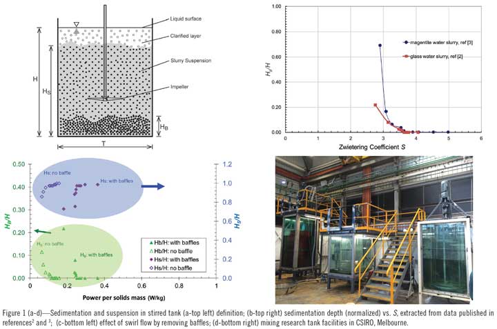
Of interest are the sedimentation depth HB and the solids dispersion height HS as defined in Figure 1(a). Figure 1(b) presents HB (normalized by H, the liquid height) as a function of S, determined from measurement. This curve is agitator design specific, but is independent of tank size. Once determined from measurements, e.g., in laboratory small scale tests, this curve can be used to assess sedimentation depth in a large tank for assessing the effect of variables such as particle size, impeller speed and diameter as implied in eq. (1). In Figure 1(b), solids could be said to be fully suspended when S>3.90 (~); sedimentation could be considered extreme for S<3.
In our approach, Figure 1(b) is used to assess the status of sedimentation initially, followed by assessing the feasibility of changing the parameters in eq. (1) to increase S in order to solve a sedimentation problem, e.g., by increasing agitator speed or diameter or other parameters1. However, agitator power capacity and cost can often be limiting factors, such that it may be impractical to increase the speed. This problem can be overcome by adopting swirl flow design with removal of baffles. In such a change, the curve of S is typically found not to be greatly changed, but power is dramatically reduced (e.g., by ~30-50%). This allows an increase in speed or diameter to operate at a higher S parameter at an identical power input. This usually leads to increased off-bottom suspension and improved solids mixing and dispersion.
Figure 1(c) illustrates a typical laboratory test result demonstrating application of a swirl flow design by removing baffles; it shows that a reduced sedimentation depth (HB/H) is achieved at the same power requirement, but at a higher speed. Enhanced off-bottom suspension tends to correlate with enhanced dispersion of solids, as evident from increased HS/H when baffles are removed. Increased slurry dispersion height (HS) corresponds to reduced stratification and improved blending of solids of different densities. Figure 1(d) shows a recent photo of the slurry mixing research test tank at CSIRO in Australia (Melbourne).
Here are a few examples of how application of swirl flow agitation design has resulted in favorable results at commercial operations.
 LKAB, Sweden
A total of eight iron-ore slurry surge tanks (each ~4,000 m3 capacity) are employed by LKAB at Kiruna, Sweden. Some of these tanks have, for many years, experienced inadequate stirring that reduced surge capacity and resulted in production loss due to stoppages at the concentration and pelletizing plants. LKAB commissioned CSIRO to conduct an experimental research using laboratory modeling. It was concluded from small-scale tests that the original four-bladed, axial-flow impeller located near the bottom could be made to provide improved off-bottom suspension and dramatically better mixing at approximately the same power input by using swirl flow after the tank baffles were removed. A larger impeller diameter was required to maintain the same power input after baffle removal. This research result was implemented in one of LKAB’s full-scale slurry tanks (Figure 2), achieving a successful outcome of more consistent blending, which allowed ~50% increase in tank surge capacity.
 Queensland Alumina, Australia
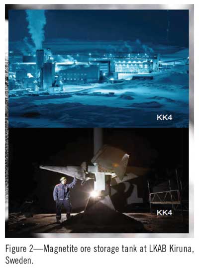
Essentially the same swirl flow agitation approach applied at LKAB Kiruna was also used in bauxite slurry holding tanks at Queensland Alumina (QAL) to solve a sedimentation-related agitator bogging problem that caused frequent shutdowns and reduced tank-online campaign time. Swirl flow in QAL’s nine slurry holding tanks (Figure 3) was achieved by removing all four vertical baffles while retaining the original Lightning A310 impellers (three or four impellers). Additional motor power capacity became available after baffles were removed, allowing an extension of the bottom impeller diameter to improve off-bottom solids suspension and resulting reduced build-up of sedimentation solids. This modification, carried out in 2013, improved tank reliability with online time for HT2 extended from ~3-4 months to ~13 months.
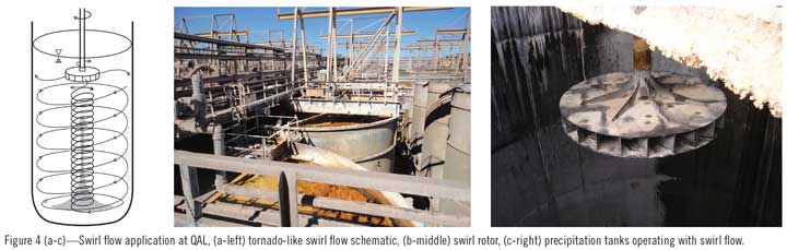
Swirl flow can also be generated by a single radial impeller located at the tank top, as schematically shown in Figure 4 (a). In this design (patented), a swirling flow pattern picks up solids from the base of the tank, lifts them and mixes them well as they swirl around the outside of the tank and return to the base of the tank. The flow pattern is very similar to that of a tornado in the natural environment. Due to the short shaft design, this swirl design experiences significantly less force loading than in baffled agitator systems or draft tube structures used in traditional mixing systems. This results in substantial capital cost savings and high mechanical reliability.
QAL has been replacing broken draft tube agitators with swirl flow designs in their precipitation tanks since 1997; currently, there are 21 precipitation tanks operating with swirl flow at QAL (Figure 4(b) and (c)). Swirl flow agitator systems typically cost a small fraction of conventional draft tube systems at QAL, and due to their short shaft design swirl rotors do not experience mechanical failure. Swirl rotors operate at a lower tip speed than conventional agitation systems and therefore have much lower wear rates and cause less attrition to particles. One distinct advantage of the swirling motion is higher wall velocity, which acts to “self-clean” the walls of the reactor; this suppresses scale growth, reduces downtime and the need for de-scaling maintenance. Successful application of swirl flow at QAL has improved the operating factor of the converted tanks, increasing both plant yield and capacity.
With its demonstrated advantages of improved mixing, reduced capital cost and improved reliability in lowering operating costs, the CSIRO swirl flow technology is attracting attention from mineral producers and is now being rolled out across several application sectors, including bauxite/alumina, iron ore, zinc and uranium. For more details, contact jie.wu@csiro.au.
Dr. Jie Wu and Bon Nguyen are affiliated with the Fluids Engineering Laboratory, Mineral Resources, CSIRO, Australia. Steven Wang is research fellow, ETH, Zurich, Switzerland. Tom Connor is production analyst, Queensland Alumina Ltd., Queensland, Australia. Marjavaara Daniel and Erikson Ola are senior research engineers, LKAB Technology & Business Development, Kiruna, Switzerland.
References
- Zwietering TN., 1958. Suspension of Solids in Liquid by Agitators. Chem. Eng. Sci. 8, 244–253.
- Wu, J., et al., 2011. AIChE Journal 57(9), 2316-2324.
- Wu, J., et al. 2016 (in press), Chemical Engineering Technology.


