


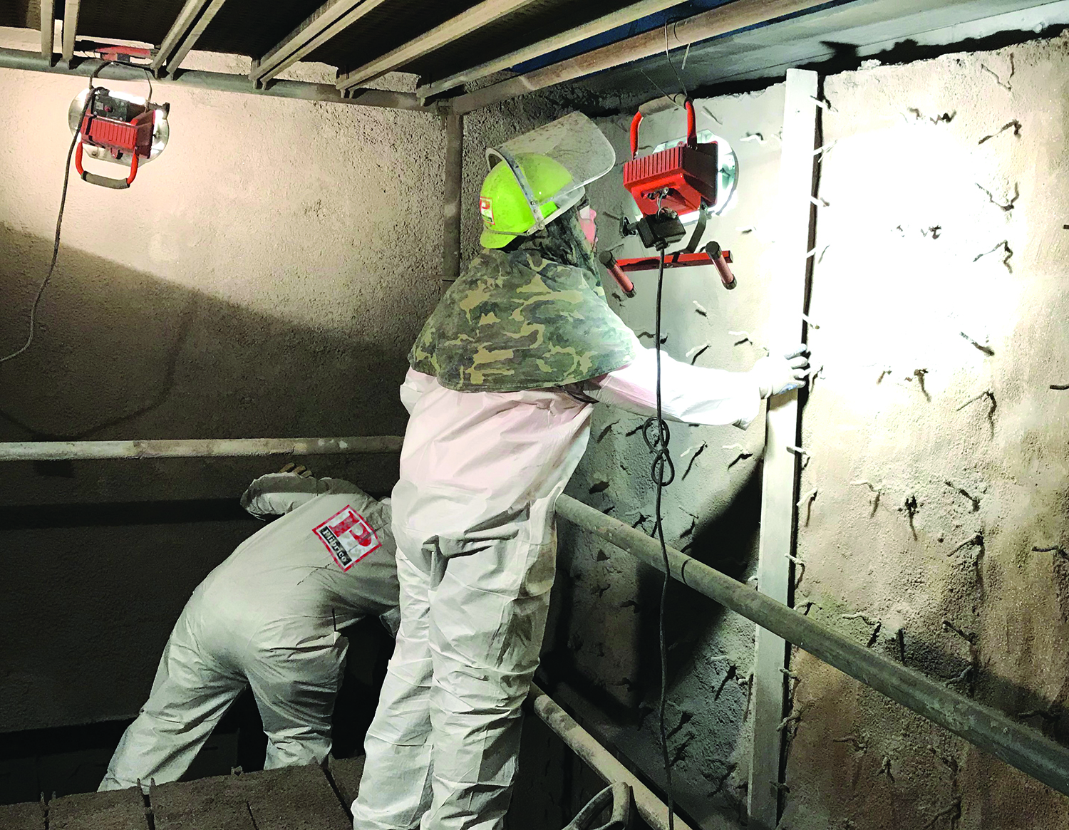
Following industry-standard recommendations for refractory anchor installation can increase service life and maximize refractory performance.
It is estimated that up to 40% of refractory lining failures can be attributed to a problem with the design of the anchor system or improper installation. This is a significant number. When designing a refractory lining for an industrial application, anchor design becomes one of the most important factors in creating a robust lining that is supported properly. In particular, the tips of the anchors experience the highest temperatures because they are closest to the hot face and thus become an important consideration.
Anchors have several functions. They hold the refractory to the wall to keep it from falling in. They also prevent wall buckling due to the internal thermal stresses created by high temperatures. And, to a lesser degree, anchors can also help support the load of the refractory weight.
To create a monolithic refractory lining that is properly supported and maximizes service life, here are three important metallic anchor tips to know.
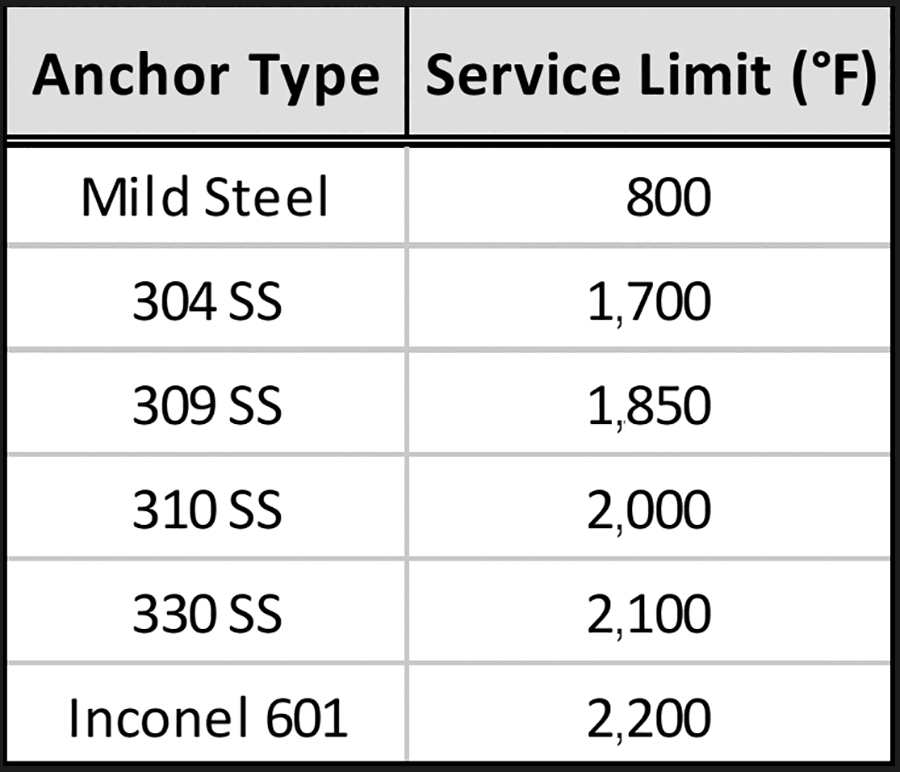
Recommended anchor tip temperature limits for various common alloys.
Type and Temperature
For refractory linings in which metallic anchor systems are used, refractory engineers and designers almost always use Class III austenitic stainless-steel anchors of various qualities. The typical grades of stainless steel used are AISI 304, 309 and 310. These contain chromium and nickel to provide the best corrosion resistance and ductility at high temperatures. For some applications in which temperatures are more extreme, and the use of ceramic tile anchors is not practical for various reasons, AISI 330 and even Inconel 601 is sometimes used. These anchors have higher nickel content for superior oxidation resistance and tensile strength at temperatures of 2,000°F or higher. Inconel 601 gives the added advantage of good resistance to both carburization and sulfidation in extreme applications.
Best Practices
Anchor sizing for a refractory lining depends on the refractory thickness and number of components. Some designers use the practice of sizing the anchor height to be 75%-85% through the main dense castable or gunned lining. Other rules of thumb used in the industry dictate that the anchor tip should be no more than 2 in. from the hot face of the refractory for thicker lining designs greater than 6-7 in.
For refractory applications, it is useful to know the temperature gradient through the refractory lining, from the hot face to the cold face, to choose the proper anchor size so that one doesn’t exceed the temperature limit of the alloy being used. To help calculate the correct temperatures at different points in the refractory lining, many industry professionals will use a heat loss calculator/estimator, which enables the user to choose the proper anchor height by determining the anchor tip temperature it will experience. There are numerous heat loss applications that can estimate the cold face of a furnace lining given the input conditions of a thermal unit. As part of its value-added service as a refractory solutions provider, Plibrico Co. LLC has a Web-based heat loss application that gives a good estimation of the thermal gradient of the refractory lining from hot face to cold face to maximize the anchor thermal performance.
For example, in the accompanying diagram, one can see a 9-in. side wall of refractory lining using 6 in. of a typical 60% alumina low-cement castable and 3 in. of 2,300°F lightweight insulating castable for an application operating at 2,000°F with an ambient temperature of 80°F. For this application, they would select 309 SS or 310 SS metallic anchors because the intermediate temperature at about 80% of the main lining thickness is approximately 1,900°F. Although 304 SS anchors would be more cost effective and are most commonly used in the industry, the anchor tips would oxidize at this temperature and would essentially burn out.
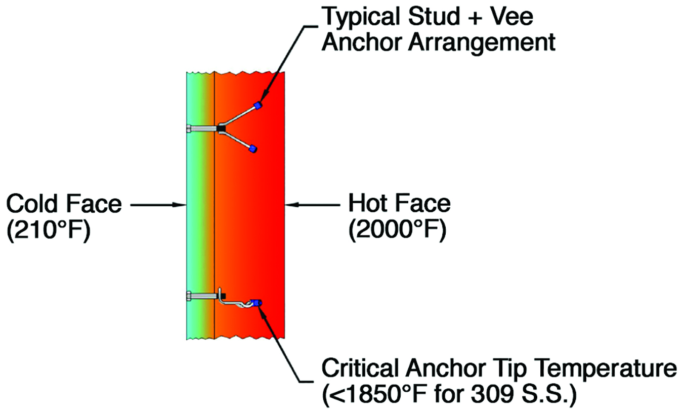
Typical refractory anchor lining configuration.
A Word on Anchor Tips
Standard practice for years has been to allow for expansion of the anchor tines by covering the anchor tips with plastic caps, dipping them in a wax, or putting tape on them. Metallic anchors expand at about three times the rate of alumino-silicate refractories. The expansion material affixed to the anchor tips burns out at low temperature and allows the anchor a space to expand without causing cracks in the refractory.
Best practices in metallic anchor design also must include anchor spacing. As a function of the specific equipment and geometry size, refractory engineers must consider the specific installation area. For example, anchor spacing patterns will be different in a flat wall or roof, as compared to a section that has a transition of geometry or a less critical area of a vessel.
Anchor spacing should be based on the features of each specific project, such as mechanical properties of the anchor, and the refractory lining as a function of the temperature. Refractory engineers will use these properties in mathematical models to help create the optimal anchor spacing pattern and plan.
Often, failures commonly attributed to the refractory component can, in fact, be caused by deficiencies in the anchoring system. A robust anchoring system is key to maintaining monolithic refractory lining integrity, even when it is cracked, to prevent a total structural collapse.
To prevent vessel lining failures, increase service life, and maximize refractory performance, incorporate these metallic anchor recommendations. With these tips, it is possible to design and optimize an anchoring system that will work well with the demanding needs of refractory linings today.
For more information about metallic anchors and refractory anchoring systems, contact the Plibrico Co. at contact@plibrico.com or +312-337-9000.
Dan Szynal is vice president of engineering and technical service for the Plibrico Co.


