


Shifting conveyors in a large IPCC system is time consuming, hard on equipment, and difficult for operators to accomplish quickly and efficiently. Dozer automation could alleviate these problems.
By Robert Ritter, Andre Herzog and Dr. Carsten Drebenstedt
 |
| Figure 1—In-pit crusher station distribution by region and type. |
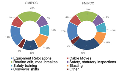 |
| Figure 2—Breakdown of process downtime for SMIPCC and FMIPCC systems. |
In-pit crushing and conveying systems (IPCC) have gained increasing interest over the last decade. For future mines with high strip ratios, long travel distances and high fleet costs, IPCC systems offer great potential to reduce operating costs. IPCC systems are generally differentiated, based on the mobility of the crusher station, into fixed, semimobile (SMIPCC) and fully mobile (FMIPCC) variations. A survey1 conducted by the authors on in-pit crusher population revealed that, since 1956, 447 in-pit crusher stations have been installed, are currently in the erection/manufacturing stages or are on order. Figure 1 shows the distribution of in-pit crusher stations by region; the pie charts indicate the distribution of crusher station type and the total number of crusher stations since 1956. The black dots indicate the locations of in-pit crusher stations used for large mining operations past 1970.
An important part of the operation of these systems is the influence of scheduled process downtime on effective production time. Conveyor shifting procedures represent a major share of process downtime for SMIPCC and FMIPCC systems, accounting for approximately 14% and 24%, respectively, in total process downtime for a typical surface mine (Figure 2).
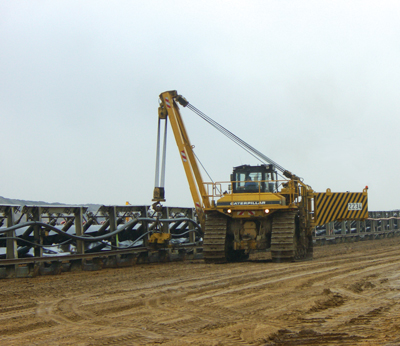
Belt conveyors must be shifted to follow the operating face or dump face advance. This operation is commonly accomplished using pipe layer-fitted bulldozers with a track-shifting head (Figure 3). The dozer engages the conveyor and applies lateral shifting forces to move the conveyor structure without the need to dismantle the conveyor. Three shifting patterns are possible:
- Parallel shifting, in which all modules of the shiftable conveyor are shifted over the same distance;
- Radial shifting, where one end (head or tail end) of the conveyor remains in the same position and functions as a pivot point while the other end is swung around; and
- Combined shifting, which uses both parallel and radial shifting techniques so that one end of the conveyor is shifted further than the other.
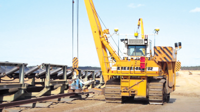
 |
| Figure 3—Common pipe layer used as IPCC shifting unit. |
 |
| Figure 5—Example of the impact on conveyor system components from the shifting process. |
Time needed for shifting depends on ground conditions, conveyor length, shifting width, and available workers and equipment. It typically takes 8–24 hours and is split up into four processes (depending on length alteration), including preparation for shifting, shifting process, alignment and startup. Minimum downtime can be achieved by employing a radial shifting pattern without length alteration. Conveyor shifting has typically been accomplished using standard pipe layers or crawler excavators. This approach carries certain problems that need to be addressed:
- Constant conveyor shifting over a long distance (e.g., 1,500 m) will result in horizontal and vertical misalignment, no matter how carefully it is done.
This is due in part to:
- variations on soil,
- weather conditions, and
- the shifted unit—in terms of physical conveyor length and time needed to straighten “waves” in the structure.
- The terrain between the current conveyor location and its final position must be checked and if necessary prepared to avoid sinus lines from soil bumps and depressions. Evaluation of soil unevenness and any necessary subgrade work before shifting might lengthen the whole process—although this work can be done in advance.
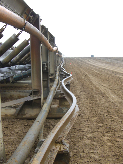
- The shifting process itself (Figure 4) has a high impact on the useful life of the conveyor system. Mechanical stress during the shifting process often results in material wear, fatigue and fracture (Figure 5), additionally facilitated by seasonal temperature differences. Repair of structural damage to the conveyor system during the shifting process is a major factor in downtime.
- Pipe layers, crawler excavators or dozers have a shorter useful service life when they are used for conveyor or track shifting duties, from carrying the constant heavy load of the conveyor system. Most standard dozer and crawler chassis are not designed to handle such heavy side-loads for extended periods, resulting in overstress on the crawler tracks. Furthermore, unfavorable soil conditions can easily double or triple the load. Decreased useful service life means higher maintenance and replacement costs for those machines.
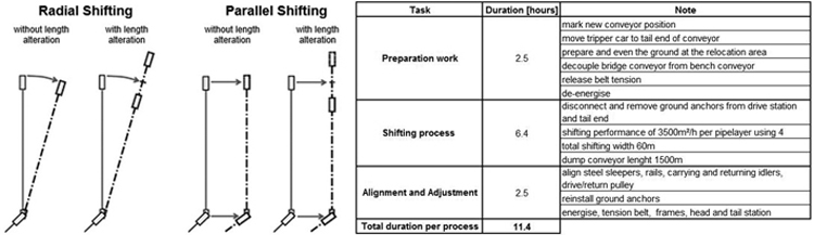 Figure 4—Schematic diagram of possible shifting patterns.2
Modern, state-of-the-art shifting equipment can be divided into two main groups: modified pipe layers, as shown in Figure 6; and dual-use belt reverse crawler tractors, shown in Figure 7, that also can perform subgrading. Both offer certain features that improve accuracy and work speed, and on the other hand, prolong their own service life and that of the conveyor system as well.
These include:
- Georeferencing measurement capability before and during the shifting operation to avoid curves and sinus lines caused by improper subgrades.
- Additional force measurement on the track-shifting or pulley head to avoid slack rope and overload conditions.
- Manual crawler track slip control, which allows the operator to separately adjust track speeds. The dozer performs so a bow ride during the forwarded track shifting process and increases the load pull ability significantly (Figure 8).
However, these abilities generate increased information inputs for the operator to handle during the shifting process, and operators must pay close attention to monitor and adjust settings when needed. Because of this, there has been a growing interest to develop a shifting system that lightens the operator’s workload from these preparation, adjustment and evaluation tasks.
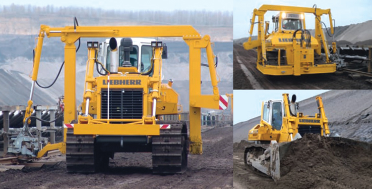
 |
| Figure 6—Modified state-of-the-art pipe layer used as IPCC shifting unit. |
 |
| Figure 7—Dual use belt reverse crawler tractors for IPCC shifting and subgrading. |
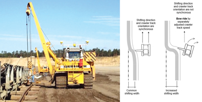 |
| Figure 8—Bow ride uses differential track speeds. |
In the light of this consideration, the authors developed an improved conveyor shifting unit that provides automatic capabilities; machine handling is now a drive-by-wire operation. The onboard process computer is directly attached to the dozer’s OEM controls, monitors all essential parameters, and intervenes automatically when needed to protect the shifting unit and the conveyor. This capability extends to slip control, force measurement and subgrade control. The whole shifting process is digitally planned within the overall mining terrain model; the system compares current conveyor location and the expected final position by GPS and deviations are displayed automatically to the dozer operator.
Digital job billing and machine status reporting will automatically be transmitted after scheduled work objectives are done. This experimental conveyor shifting unit is a prototype based on the current Liebherr RL Pipelayer series and is physically different from a typical machine due to three main modifications:
- GPS equipment for speed measuring, georeferencing and signal indication of the required final position for the machine operator.
- A force-measuring device on the winch.
- A process computer that is connected to the OEM machine bus control. The computer determines required speed and slippage for each crawler track. The machine operator needs only to determine direction, forward or backward. The process computer compares scheduled job parameters for the shifting process with current GPS data and monitors significant machine parameters. All data are transmitted by radio to the mine supervising dispatcher.
Field tests under real-life conditions at a lignite mine in Germany have shown that the drive-by-wire concept significantly speeds up the shifting process. A job there involving two pipe layers, 4,000 m of conveyor length and total shifting width of 100 m, was accomplished within 8 hours. Typically, eight pipe layers had been required to achieve the same results.
Based on these results in conveyor shifting unit automation, the institute of mining and special underground engineering at the University of Mining and Technology in Freiberg plans further development of an autonomous conveyor shifting dozer prototype that is able to perform shifting and preparatory subgrade work without a human operator.
Robert Ritter (robert.ritter@mabb.tu-freiberg.de) studied industrial engineering with a specialization in mining engineering and finance at the University of Mining and Technology Freiberg and University of Alberta. In 2012, he joined Sandvik’s mine planning department, where he carries out studies to ensure customers receive maximum value by selecting the right mining solution and application. He also is a Ph.D candidate at the University of Mining and Technology in Freiberg, researching development of an analytical method to determine the capacity of IPCC systems.
André Herzog (andre.herzog@extern.tu-freiberg.de) studied electrical engineering with a specialization in robotic engineering at the Brandenburg University of Technology Cottbus. Since 2010, he has worked with mining equipment subcontractors in Germany to develop prototypes for earthmoving and soil improvement machines. He also is a Ph.D candidate at the University of Mining and Technology in Freiberg, researching development of general-purpose robot systems for mining processes. Dr. Carsten Drebensted is a professor at the University of Mining and Technology in Freiberg.


